Kin_001 Hydrocarbon kinetics in uniaxial column with deposition
This example provides an introduction to hydrocarbon kinetics using a coupled thermo-hydro-mechanical (THM) modelling strategy in a 2D sedimentation column using ParaGeo. Features of the example are:
1THM sedimentation modelling.
2Hydrocarbon generation from kerogen oil and gas generative layers.
3Pore pressure generation due to the hydrocarbon kinetics.
4Influence of kerogen thickness on the pore pressure generated.
5Porosity update flag to consider or not the porosity change due to hydrocarbon expulsion.
6Strength update (or reduction) factor fφ due to porosity change.
7Multiple kerogen generative layers in sedimentation column (four layers of kerogen 'B').
8Different type of kerogen generative layers in sedimentation column (two layers of kerogen 'B' and two layers of kerogen 'F').
9Combined use of two damping models - mass proportional damping and bulk viscosity damping to aid the numerical stability of the long 8000m x 100m column.
The example documentation assumes that the user is familiar with layer sedimentation and hydrocarbon maturation modelling. If not familiar, the following examples are recommended to be undertaken beforehand:
1HM_004 - Uniaxial Sedimentation using Layer Deposition.
2Val_005 - Hydrocarbon Maturation Validation.
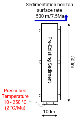
The objective is to simulate the generation of hydrocarbon in the kerogen generative layers of a sedimentation column which is subjected to an increasing burial temperature of 10 - 250 °C at the base, increasing at a rate of 2 °C/Ma (Pepper and Corvi, 1995). Investigations into the following factors affecting the hydrocarbon generation and the influence of the generation are also presented: •Influence of thickness of kerogen layers on hydrocarbon generation. •Influence of porosity increase due to hydrocarbon expulsion on pore pressure generation. •Reduction in strength of sediment due to porosity increase due to hydrocarbon expulsion. •Interaction of multiple kerogen generative layers in the single column with same kerogen type 'B' and different kerogen types 'B' and 'F'. Note that kerogen 'B' has 54.3% inert kerogen and kerogen 'F' has 88% inert kerogen.
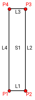
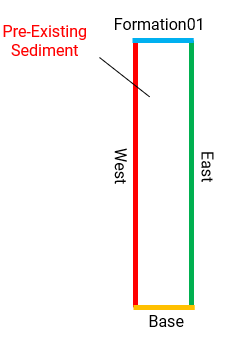
500m of pre-existing sediment is represented and sedimentation and consolidation of the 7500m of sediment over a period of 120 Ma is represented by the 'absolute' sedimentation algorithm. Two kerogen generative types are represented in the models - kerogen 'B' and kerogen 'F' and these kerogen generative layers are defined with high total organic carbon content TOC of 20% to clearly demonstrate the influence of various kerogen kinetics parameters. The model is analysed in uniaxial strain conditions; i.e. the vertical sides of the model are constrained in the horizontal direction, and the base of the model is constrained in the vertical direction. Gravity load for the pre-existing sediment is applied over 7.5 Ma using a step_ramp load curve and sedimentation of the 7500m of sediment takes place between 7.5 and 120Ma with the target sedimentation horizon surface moving at a rate of 500m per 7.5Ma in 15 depositional layers. A top surface load of 0.2 MPa is also applied to the column using a step_ramp load curve.
Unstructured triangle (TPM3V) is used with a target element size of 20m. Adaptive remeshing is utilised for the sedimentation process and remeshing is triggered at a distortion of 15% with the objective of maintaining the element size at 20m. Hydrocarbon kinetics variables are monitored with a history output at a point in each of the kerogen generative layers. History section line output data in .las format along the length of the model are also output at the end of every stage. These monitored data includes temperature, pore pressure, hydrostatic pore pressure, porosity, stresses and kinetic KTR kerogen transformation ratio (if applicable).
Units of the model for stress, length, time and temperature are MPa, m, Ma and Celsius respectively.
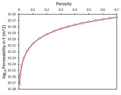
Material Properties The material "Shale_avg" in the material file "Shale_Average.mat" corresponds to an average Shale material characterisation utilizing a poro-elastoplastic constitutive SR4 plastic material model with hardening data based on the Cam Clay analytical model. A transverse isotropic porosity dependent permeability relationship is also utilized. The material property parameters for this material are:
The additional material parameters related to the porous flow and thermal fields are:
Fluid Properties The properties of the pore fluid must be specified. The principal parameters are:
|
A total of seven case models are simulated as shown in the table below:
|
These seven case models demonstrate the following investigations:
•Influence of strength update (or reduction) factor due to porosity increase from kerogen -> hydrocarbon transformation - Case01a vs Case01b vs Case01c.
•Influence of kerogen layer thickness and demonstration of different kerogen types interacting in the single column - Case02 vs Case03.
•Influence of porosity change due to kerogen -> hydrocarbon transformation - Case01a vs Case04.
The base case (Case00) model with no kerogen will serve as a reference to all simulation cases.
Simulation Cases
The data files for the examples are found in: ParaGeo_Tutorial_Examples\Kin_001
Case 00 Base Case with no kerogen
Case 01 Four layers with kerogen 'B' and strength update factor
Case 02 Two layers with kerogen 'B' and two layers with kerogen 'F'
Case 03 Kerogen layer thickness
Case 04 Hydrocarbon kinetics porosity update flag
A full description of the data required for the uniaxial sedimentation column with no kerogen is provided in Case00 Base Case description. Subsequent cases containing kerogen in the layers will only contain description of hydrocarbon kinetics related data.
References
[1] Pepper, A.S. and Corvi, P.J. (1995(a)): Simple kinetic models of petroleum formation. Part I: Oil and gas generation from kerogen. Marine and Petroleum Geology. 12(3) 291–319. 1995(a). [2] Pepper, A.S., Dodd, T.A. (1995): Simple kinetic models of petroleum formation. Part II: Oil-gas cracking. Marine and Petroleum Geology. 12(3) 321-340. [3] Pepper, A.S. and Corvi, P.J. (1995(b)): Simple kinetic models of petroleum formation. Part III: Modelling an open system. Marine and Petroleum Geology. 12(4) 417-452.
|


