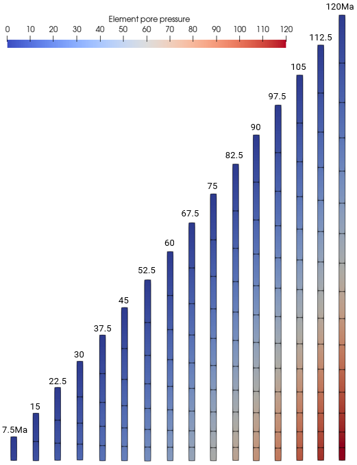
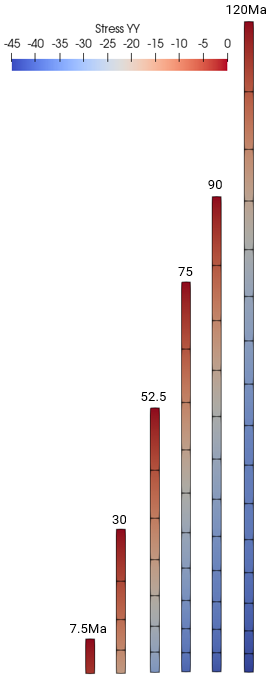
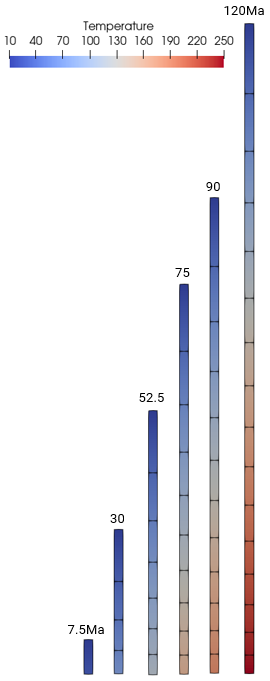
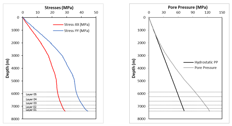
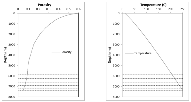
The data file for the project is in : Kin_001\Case00\Data. The basic data for Case 00 with no kerogen includes:
1Mesh_generation_variables defining system settings for mesh generation with perturbation to give a less regular mesh. 2Units defining stress in "MPa", length in "m", time in "Ma" and temperature in "Celsius". 3Geometry_set data defining model boundaries and stratigraphy horizon. 4Stratigraphy_definition, Stratigraphy_horizon and Stratigraphy_surface_load defining stratigraphy data for the pre-existing layer. 5Sedimentation_parameters, Sedimentation_horizon and Sedimentation_data defining the sedimentation data for the 15 new sediment layers using a "Step_ramp" time curve. 6Group_control_data activates geomechanical, seepage flow and thermal fields for the pre-existing group and Group_data defines the element type, material name, porous flow type, etc associated with the group. 7Material_data to read in the "Shale_avg" material properties and the Fluid_properties contained in the external material file "Shale_Average.mat" which defines the material properties of the pre-existing and all sedimentation layers. 8Support data (Support_data) defining: (a) Geomechanical field: Base fixed vertically and sides fixed horizontally. (b) Thermal field: Base is defined as prescribed for a temperature loading. 9Damping_global_data defining the use of combined damping models (mass proportional damping of 0.5% and bulk viscosity damping with constant of 0.5) to aid the numerical stability of the long 8000m x 100m column. 10Basal temperature loading of 10° to 250° at a rate of 2°/Ma defined using Global_loads, Time_curve_data and Load_case_control_data. 11Gravity data (Gravity_data) applied with "Step_ramp" time curve. 12Data required to define geostatic initialization (Geostatic_data) with hydrostatic pore pressure using a "Step_ramp" time curve. 13Mesh control (Mesh_control_data) and unstructured mesh generation data (Unstructured_mesh_data) defining a constant mesh size of 20m with perturbation defined for the mesh generation to give a less regular mesh (Mesh_generation_variables). 14Adaptivity control (Adaptivity_control_data) and adaptivity set data (Adaptivity_set_data) specifying a remeshing check every 100 steps with remeshing triggered at a distortion of 15% with the objective of maintaining the element size at 20m. 15History data for a line path along the middle of the column (History_section_line) to output variables such as temperature, pore pressure, hydrostatic pore pressure, porosity and stresses at the end of every stage. 16Point history (History_point) data to output stresses, pore pressure, temperature and porosity at the base of the first five layers every 1.0 Ma. 17Coupling data (Couple_control_data) to define an incremental coupling between the geomechanical, fluid flow and thermal fields using the variable group volume strain update algorithm based on undrained conditions. 18Control data (Control_data) defining: (a) Incremental transient solution algorithm (Type 4), (b) Duration of 7.5 Ma, (c) Flow/Thermal time increment of 0.0375 (i.e. coupling time step of 0.0375Ma, therefore 200 coupling times for stage duration of 7.5Ma). (d) Target number of mechanical steps per coupling step set to 150. (e) Plot file every 3.75 Ma (i.e. two plotfiles per stage). (f) Screen message output every 10 flow/thermal increments. 19 Geometry data (nodal_data, Geometry_line and Geometry_surface) for definition of the pre-existing layer geometry (100m x 500m column).
Following are descriptions of some key data. Note that these data descriptions are not in the same order as they appear in the data file.
The stratigraphy data associated with the pre-existing sediment comprise:
•Stratigraphy_definition - defines the unit name and basal horizon. For simplicity of stratigraphy data definition, the stratigraphy unit name and stratigraphy horizon name are defined with identical name to the Group_data name of "Formation01". When this same naming convention is used, Horizon_numbers and Group_numbers are automatically set and need not be defined. •Stratigraphy_horizon - defines the top horizon geometry for the stratigraphy unit. •Stratigraphy_surface_load - define stratigraphy surface loading for mechanical stress, pore pressure and temperature.
Note that in order to determine the thickness data relevant to the hydrocarbon kinetics in subsequent cases, the stratigraphy data require definition of both the base and top of the pre-existing unit.
Data File
|
|
* Stratigraphy_definition
Units IDM=1
"Formation01"
Basal_horizon "Base"
* Stratigraphy_horizon NUM=1
Name "Formation01"
Geometry_set "Top"
* Stratigraphy_surface_load
Applied_stress 0.2
Time_curve_stress "Step_ramp"
Pore_pressure_flag 1
Temperature_flag 1
Temperature 10.0
Time_curve_temperature "Step_ramp"
|
1Stratigraphy definition data: a.Stratigraphy unit name defined as "Formation01" - same as the Group_data name. b.Basal horizon defined as geometry set named "Base".
2Stratigraphy horizon data for stratigraphy unit "Formation01": a.Stratigraphy horizon name also defined as "Formation01" for consistency. b.Top surface of unit is defined by geometry set named "Top".
3Stratigraphy surface load defined with: a.Mechanical stress load of 0.2MPa applied to the top surface via a "Step_ramp" load curve. b.Prescribed temperature of 10 °C on the top surface via a "Step_ramp" load curve. |
|
Data File
|
|
* Geostatic_data NUM=1
Name "Initial"
Groups IDM=1
"Formation01"
Pore_pressure_distribution "Hydrostatic"
Time_curve "Step_ramp"
|
1Geostatic data is defined for the initialization of the pre-existing sediment group named "Formation01" with hydrostatic pore pressure utilizing a "Step_ramp" time curve.
|
|
Layer sedimentation is defined using three data structures:
1Sedimentation_parameters defining the data that is common to all sedimentation layers. This data structure is defined at the start before the first control stage. 2Sedimentation_horizon defining the moving target topology for the stratigraphy horizon of the new layers using a displacement time curve. This data structure is defined at the start before the first control stage. 3Sedimentation_data defining the stratigraphy unit name. This data structure is defined in each sedimentation stage with the new stratigraphy unit name for the deposited layer.
Sedimentation_parameters
•This data structure is defined at the start before the first control stage and contains data that is common to all sedimentation layers.
Data File
|
|
* Sedimentation_parameters
Sediment_horizon_name "General"
Sedimentation_type "Absolute"
Material_name "Shale_avg"
Material_file "Shale_Average.mat"
Duration 7.5
Time_curve "Step_ramp"
|
1The target Sediment_horizon_name is "General". 2The sedimentation horizon type is "Absolute". 3The material defined for the new layers is the same as the pre-existing sediment, i.e. "Shale_avg" read in from the material file "Shale_Average.mat". 4The gravity for the new layer is applied over 7.5Ma using the "Step_ramp" time curve. |
Sedimentation_horizon
•This data structure is defined at the start before the first control stage and defines a moving target topology for the stratigraphy horizon of the new layers using a displacement time curve. The target horizon is moving at a rate of 500m/7.5 Ma, therefore for the 15 new layers, the final horizon has displaced 7500m in 112.5Ma, i.e. total height of 8000m with initial height at the top of the pre-existing layer at 500m.
Data File
|
|
* Sedimentation_horizon NUM=1
Name "General"
Facet_topology IDM=2 JDM=1
1 2
Coordinates IDM=2 JDM=2
-10.0 500.0
110.0 500.0
Time_curve 1000
Displacement IDM=2
0.0 7500.0
* Load_curve_data NUM=1000
Time_curve IDM=2
0.0 112.5
Load_factor IDM=2
0.0 1.0
|
1A single moving sedimentation horizon named "General" is defined. 2The horizon is defined by a single facet with two nodes at locations:
Node
|
X-Coordinate
|
Y-Coordinate
|
1
|
-10.0
|
500.0
|
2
|
110.0
|
500.0
|
3A final reference displacement of 7500m in the vertical direction is defined for the horizon surface. 4Load curve 1000 is assigned that defines that the full vertical displacement of the surface will be achieved after t = 112.5Ma. This equates to the surface moving at a rate of 500m/7.5Ma for each of the 15 new sediments. |
Sedimentation_data
•This data structure is defined in each sedimentation stage and the only data to be changed is the stratigraphy unit name of the new deposited layer.
Data File
|
|
* Sedimentation_data
Stratigraphy_unit_name "Formation03"
|
1The sedimentation data is defined in each sedimentation stage with the new stratigraphy unit name associated with the deposited layer.
|
|
A combined damping model (mass proportional damping and bulk viscosity damping) is adopted to aid the numerical stability of the long 8000m x 100m column.
Data File
|
|
* Damping_global_data
Damping_models IDM=2
Percentage
Bulk
Percentage_damping 0.005
Bulk_damping_model "BulkViscosity"
Bulk_damping_properties IDM=1
0.5
|
1Damping_models define the damping models to be used in combination. 2Bulk viscosity damping with constant of 0.5 is utilized. 3A small percentage damping of 0.005 is shown to improve stability when used in combination with the bulk viscosity damping. |
|
Data File
|
|
* Group_control_data
Group_numbers IDM=1
1
Active_geomechanical_groups IDM=1
1
Active_porous_flow_groups IDM=1
1
Active_thermal_groups IDM=1
1
* Group_data
Group_name "Formation01"
Element_type "TPM3V"
Material_name "Shale_avg"
Porous_flow_type 4
Surfaces IDM=1
1
|
1Group_control_data defines the geomechanical, porous flow and thermal fields active for the pre-existing sediment group.
2Group_data defines data for the pre-existing group: a.Group name is "Formation01" b.Element type used is 3-node 2D average volume plane strain element. c."Shale_avg" material is assigned.
|
|
Data File
|
|
* Support_data
Displacement_codes IDM=2 JDM=2
1 0
0 1
Displacement_code_geom_set IDM=3
"Base"
"East"
"West"
Displacement_code_geom_ass IDM=3
2 1 1
Temperature_codes IDM=1 JDM=2
0 ! Free
1 ! Prescribed
Temperature_code_geom_set IDM=1
"Base"
Temperature_code_geom_ass IDM=1
2
|
1The base of the model is constrained vertically and the sides, "East and "West", are constrained in the horizontal direction. 2A temperature constraint is defined for the base of the model which is prescribed a temperature loading. |
|
The temperature at the base of the model is prescribed a temperature of 10 - 250 ºC at a rate of 2 ºC/Ma (as in Pepper and Corvi, 1995) over the duration (120Ma) of the simulation.
Data File
|
|
* Global_loads NUM=1
Name "Basal_temp"
Prescribed_temperature IDM=1 JDM=1
1.0
Pres_temperature_geom_set IDM=1
"Base"
Pres_temperature_geom_ass IDM=1
1
* Time_curve_data NUM=1
Name "Basal_Temp_load"
Curve_type 1
Time_curve IDM=2
0.0 120.0
Time_factor IDM=2
10.0 250.0
* Load_case_control_data
Loadcases IDM=1
1
Active_load_flags IDM=1
2
|
|
|
History Section Line Data
•A single history section line data for a line path along the full length of the middle of the column are defined for output in .las format at the end of every stage. The data monitored includes temperature, pore pressure, hydrostatic pore pressure, porosity and stresses.
Data File
|
|
* History_section_line NUM=1
Name "History_line"
Output_frequency_increment -1
Point_distribution_type 0
Number_points 10
Section_type "Vertical"
Path_format 0
Formation_data_flag 1
Plan_coordinates IDM=1
50
Output_formats IDM=1
"las"
Element_data IDM=3
"Elt_temp" "Elt_pore" "Porosity"
Hydrostatic_pressure_flag 1
Stresses IDM=3
"Strs_xx" "Strs_yy" "Strs_zz"
|
1History section line data definition comprise: a.Output_frequency_increment set to -1 defines output at the end of every stage. b.Point_distribution_type set to 0 defines point distribution based on Number_points which is set to 10 (i.e. 10 points in each stage). c.The output of section line data to be based on the vertical format is defined by Section_type set to "Vertical", Path_format set to 0 and Formation_data_flag set to 1. d.Plan_coordinates set to 50 (i.e. middle of column width) defines the reference x-coordinate value. e.Output_formats defines the section line data to be output in .las format. f.The data variables to be output include element temperature, element pore pressure, porosity, stresses in X, Y and Z directions and Hydrostatic_pressure_flag set to 1 outputs the hydrostatic pore pressure.
|
History Point Data
•Two History_point data structures are defined near the base for each of the first five layers to output variables such as element temperature, element pore pressure, porosity and stresses in X, Y and Z directions.
Data File
|
|
* History_point NUM=1
Name "Formation01"
Group 1
Output_frequency_time 1.0
Point_coordinates IDM=2 JDM=1
50 50
Element_data IDM=1
"Elt_pore"
Stresses IDM=3
"Strs_xx" "Strs_yy" "Strs_zz"
* History_point NUM=2
Name "01_Kerogen"
Group 1
Output_frequency_time 1.0
Point_coordinates IDM=2 JDM=1
50 50
Element_data IDM=3
"Porosity" "Elt_temp" "Elt_pore"
|
1History point data definition for pre-existing sediment group 1 comprise: a.History_point number 1 defines the stresses and pore pressure at the point coordinates (50, 50) at the base of the layer. b.History_point number 2 defines the porosity, temperature and pore pressure at point coordinates (50, 50) at the base of the layer. c.History data is output every 1.0Ma.
2History point data definition for the second to fifth depositions layers (destined for history point output) will require changes to the data highlighted in bold. |
|
Couple Control Data
•Couple_control_data data structure defines the active fields (i.e. geomechanical, porous flow and thermal) for the analysis and additional data to control the coupling process. This is only required to be defined once before the first Control_data.
Data File
|
|
* Couple_control_data
Solution_algorithm "Incremental"
Volume_strain_coupling "Undrained"
Volume_update_model "VariableGroup"
Field_names IDM=3
"Geomechanical"
"Porous_flow"
"Thermal"
|
1Couple_control_data data structure defines the active fields (i.e. geomechanical, porous flow and thermal) for the analysis and additional data to control the coupling process. 2 An incremental staggered solution algorithm is defined. 3Volume_strain_coupling is set to "Undrained" which is more appropriate for low permeability materials like shale. 4Volume_update_model is set to "VariableGroup". |
Solution Control Data for Pre-existing Sediment and Sedimentation Layers
•The Control_data data structures here defines the coupled geomechanical/porous flow/thermal solution data for the stage. •The same Control_data is defined for the pre-existing sediment stage and sedimentation stages with only the Control_title changed for each stage.
Data File
|
|
* Control_data
Control_title "Formation01"
Duration 7.5
Solution_algorithm 4
Initial_time_increment 0.0375
Target_number_time_steps 150
Screen_message_frequency 10
Output_frequency_plotfile -1
Output_time_plotfile 3.75
Output_frequency_restart -1
|
1The key control data comprise: a.Solution_algorithm set to 4 (incremental transient algorithm) which allows more iterations in an increment if the solution is not converged. b.Initial_time_increment is set to 0.0375, i.e. coupling time step of 0.0375, therefore coupling frequency of 200 per stage. c.The Target_number_time_steps is set to 150, i.e. 150 mechanical steps per coupling step. |
|
|

