ParaGeo-Pflotran Tutorials

Contents
In this section the tutorials demonstrating ParaGeo coupling to Pflotran-OGS and Pflotran are presented. It is noted that the nomenclature convention adopted for the tutorial cases presented here is to use PFO in the case name for cases using Pflotran-OGS and PFS for cases using the standard version of Pflotran.
INDEX
Title |
Analysis Type - Features List / Utility |
Model |
ParaGeo-Pflotran-OGS coupling |
||
•Features and functionality for ParaGeo-Pflotran simulations •Notes on model building workflows |
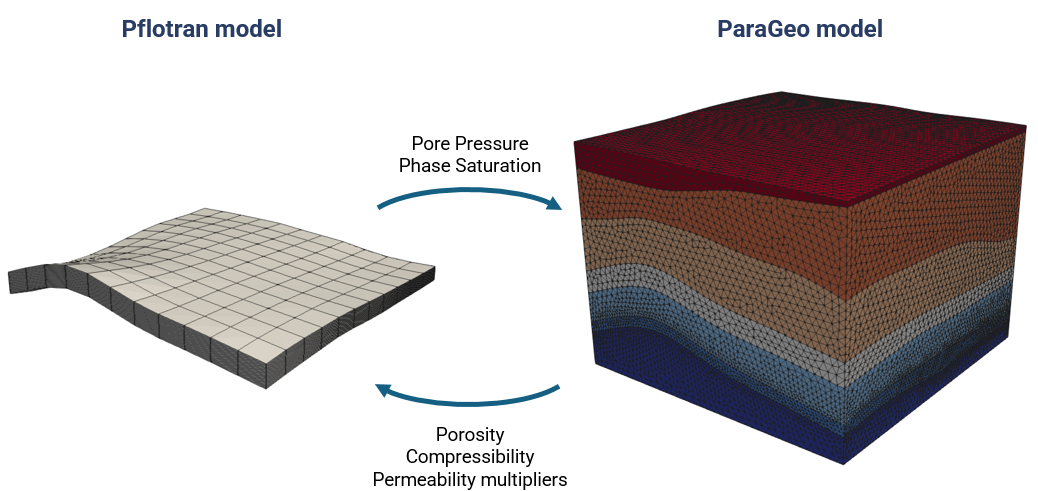
Schematic of coupling between ParaGeo and Pflotran / Pflotran-OGS where only the reservoir is solved in Pflotran (coupled group)
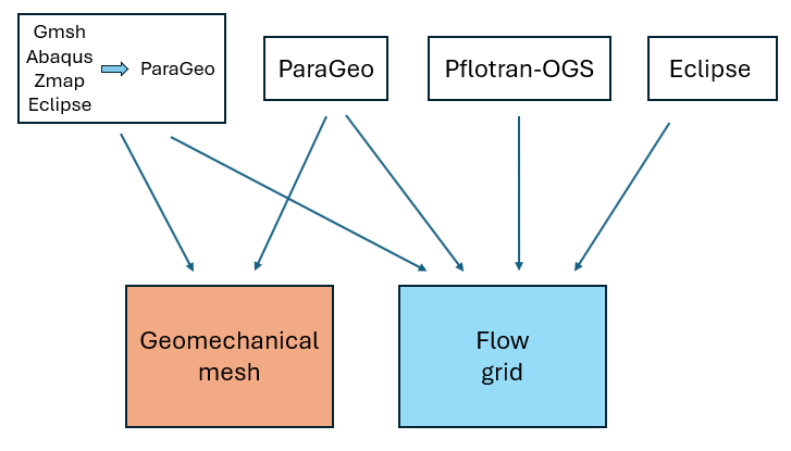
Schematic of potential mesh and grid building options for ParaGeo-Pflotran coupled simulation |
|
Coupled HM and THM (3D) |
|
|
|
•Generation of Pflotran data from ParaGeo
|
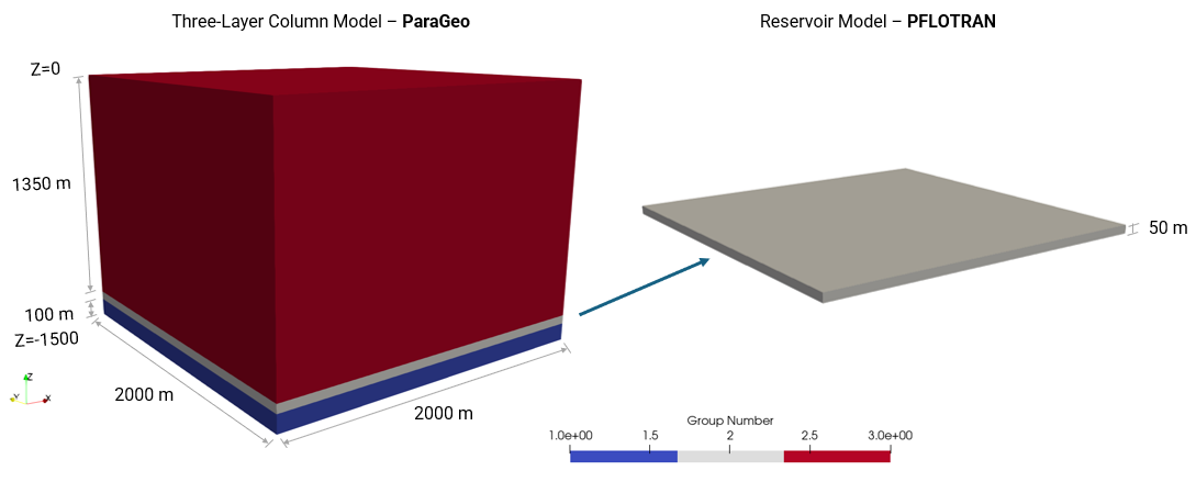
Schematic of model
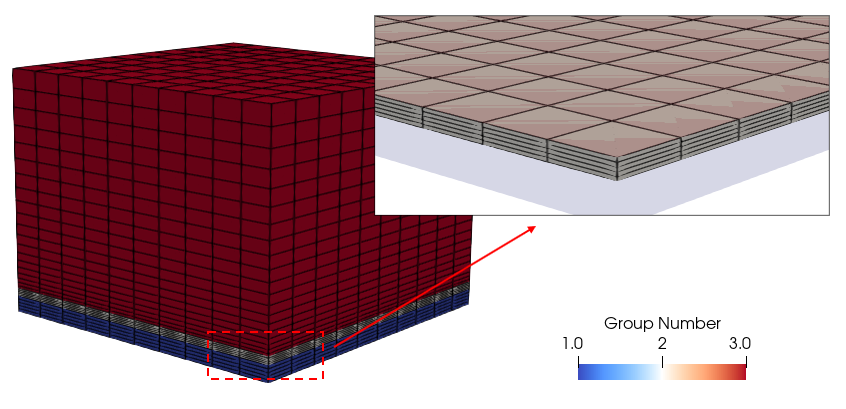
ParaGeo model mesh |
•PFO_001_Case01 Saline Aquifer oCase01a Isothermal (HM) oCase01b Transient Thermal (THM) |
•Set up of coupled simulations •Output and Visualisation of results in ParaView and ResInsight compatible formats •Demonstration of different Pflotran-OGS modelling options and scenarios |
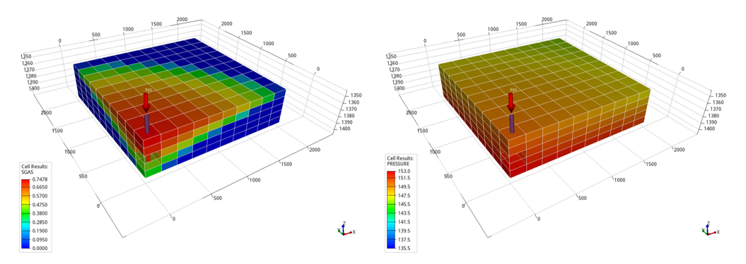
Gas saturation (left) and gas pressure (right) distributions within the reservoir after 20 years of injection
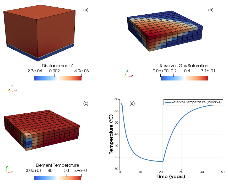
Vertical displacement (a), Reservoir gas saturation (b) and element temperature (c) distribution after 20 years of injection. Reservoir temperature evolution in a well cell (d). Figure (a) shows all the formations whereas figures (b) and (c) show the reservoir with V.E. = 10 |
•PFO_001_Case02 Depleted Gas Reservoir oCase02a COMP3 flow mode (THM) oCase02b COMP (HM) |
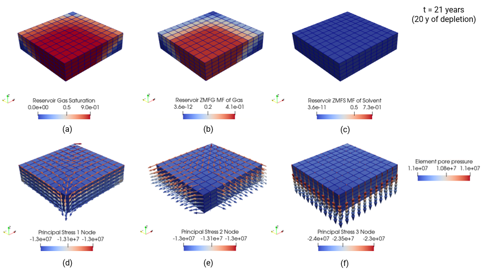
Contour plots for gas saturation (a), methane gas mass fraction (b) CO2 solvent mass fraction (c) and pore pressure with principal stress directions and magnitudes indicated by the coloured arrows (d, e, f) after 20 years of gas depletion (t =21 years) |
|
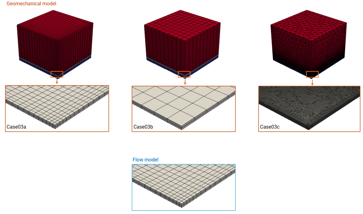
•PFO_001_Case03 Non-matching meshes (THM) •Case03a Matching meshes in reservoir for geomechanical and flow models •Case03b Coarser HEX mesh in geomechanical model •Case03c TET mesh in geomechanical model |
•Demonstration of mapping for non-matching meshes |
Various meshes simulated |