Case02 Import, Processing, Meshing and Export to a .dat and .geo file

Contents
The present example demonstrates:
1.Import of the FracMan file containing definition of a DFN
2.Processing of the fracture distribution
3.Meshing of the geometry and intersection of the discrete fractures
4.Output of the meshed geometry to a data (.dat) file and geometry (.geo) file
The data file for the example is in: Fract_001\Case02\Data\fract_001_Case02.dat. The additional data definitions compared to the previous Case01 are:
i.Geometry_set data for all model boundaries. This is not compulsory but is convenient to define it so that it will be written into the .geo file and the accompanying .GeoSumm ASCII file for future reference.
ii.Data for generation of the unstructured mesh (Mesh_control , Unstructured_mesh_data and Mesh_parameter_data).
iii.Contact_property which is required for assignment to the discrete fractures.
iv.Support_data to define prescribed displacements in all directions for the internally created geometry set "All_volumes".
v.Damping_global_data which is actually optional in the present case as no simulation will be performed.
vi.Couple_control_data which is required in the present case because we need to define a control data to run a coupled simulation. In the present case, mesh generation and intersection of fractures are to be performed, hence, the code will run an actual time step. In the previous Case01, no step was run as termination of the code was enforced prior to any intersection being carried out.
vii. Fracture_set data defined with the keyword Export_datafile_flag set to 1 will export a data file (.dat) and corresponding geo file (.geo) for use to run a simulation.
The following describes in detail the data relevant to the fracture treatment and export of the meshed geometry.
Fracture_set
In the present case Fracture_set is defined with the aim to process the original DFN and perform the intersection with the model mesh. It should be noted that we could have imported the .fab file exported in Case01 which already contains the processed DFN, however, in the present case, we demonstrate that it is possible to export the processed DFN in a FracMan file in the same workflow step as the output of the .geo file containing the discrete fracture meshed geometry.
Data File |
|
* Fracture_set NUM=1 ! ------------------------------------ Name "Set_1" Property_assignment "Frac_set1" Volume 1 Active_flag 1 Split_flag 1 Element_size 5 Pre_intersect_out_flag 0 Offset IDM=3 /Offset in X/ -40.0 /Offset in Y/ -50.0 /Offset in Z/ 0.0 Scale IDM=3 /Factor in X/ 1.25 /Factor in Y/ 2.5 /Factor in Z/ 2.0 Region_type "Rectangle" Region_size IDM=6 /X Y Z min/ 733 0 0 /X Y Z max/ 1000 210 50 Fab_file_output "frac_sample_2" Export_datafile_flag 1
* Contact_property NUM=1 ! ------------------------------------ Name "Frac_set1" (...) |
1.The data that has changed relative to Case01 is highlighted in orange. This includes:
i.Assignment of a contact property by name via Property_assignment keyword. This is compulsory during fracture intersection/split. The assigned Contact_property must be defined in the data file (not discussed).
ii.Split_flag set to 1 indicates that each fracture should be split in their hanging wall and footwall counterparts for meshing discrete fractures.
iii.Element_size defines the target size of the elements adjacent to the fractures.
iv.Pre_intersect_out_flag is defined with a value of 0 so that we perform the intersection and meshing. Note that this is the default value but is defined to highlight the difference compared to Case01.
v.Export_datafile_flag defined with 1 will export a data (.dat) file post-fracture intersection generation and stop. The corresponding geometry (.geo) file will also be generated automatically.
2.The remaining data is identical to Case01 and is not discussed here.
|
Results
The results for the project are located in Fract_001\Case02\Results. This includes:
1.The meshed geometry file (fract_001_Case02_exp.gmr) may be visualized in ParaView by loading the fract_001_Case02_exp_gmr.xmf file.
2.Several geometry plot files (fract_001_Case02_00n.gmr) may be visualized in ParaView by loading either the corresponding fract_001_Case02_gmr_00n.xmf file or the fract_001_Case02_gmr.xmf (the latter loads all the geometry plot file series).
3.The output FracMan file frac_sample_2.fab contains the processed DFN definition.
4.The frac_sample_2.fraclist ASCII file contains the list of original fracture numbers, the corresponding new fracture numbers and the fracture set being assigned.
5.The fract_001_Case02_fract_save.geo containing the geometry with the discrete fractures unsplit (file is output automatically) with the corresponding .GeoSumm ASCII file summarizing the contents in the .geo file.
6.The fract_001_Case02_exp.dat data file we requested for export containing the meshed geometry data with the split discrete fractures and the corresponding geometry (.geo) and .GeoSumm ASCII file summarizing the content in the .geo file.
In the The fract_001_Case02_exp.GeoSumm we can check that geometry sets for each fracture hanging wall and footwall counterparts have been generated as shown below.
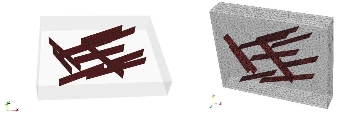
The meshed domain with the DFNs are shown in the images below.
View of the meshed domain with processed DFN output to ..._exp.dat and ..._exp.geo files
|