Case 02 Joint Normal Displacement with Bandis Model (Spacing 0.25m)
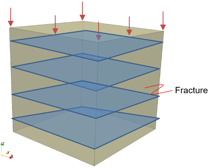
In this case, the joint spacing is reduced to 0.25m resulting in 4 joints within the simulation element. Results are compared with the 1-joint element in Case 01. Note that the data file for this Case02 differs from the Case01 data file in just the Fracture_spacing value in the Fracture_data data structure.
|
Fig. 1 Prescribed loading on element with embedded continuum fracture |
Material Properties
The properties used in this simulation test are listed below.
|
The additional material parameters related to the embedded continuum fracture are:
|
The data file for the example is in: Fract_003\Data\fract_003_case02.dat. The basic data includes: 1Material_data defines the material properties of the model, including the fracture set associated with the embedded fracture. 2Fracture_data assigns the properties of embedded fracture as well as the fracture spacing and local coordinate system. 3Global_loads prescribes axial displacement on the element top surface. 4History_point outputs displacement, stress values, and fracture state variables at every 0.01s.
Note that only key data structures are described below. |
Material_data defines the material properties of the model, including the fracture set associated with the embedded fracture.
|
Fracture_data assigns the properties of the embedded fracture as well as the fracture spacing and local coordinate system.
|
Global_loads prescribes axial displacement on the element top surface.
|
History_point outputs displacement, stress values, and fracture state variables at every 0.01s.
|
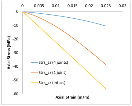
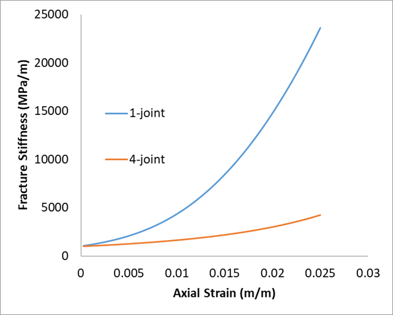
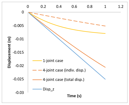
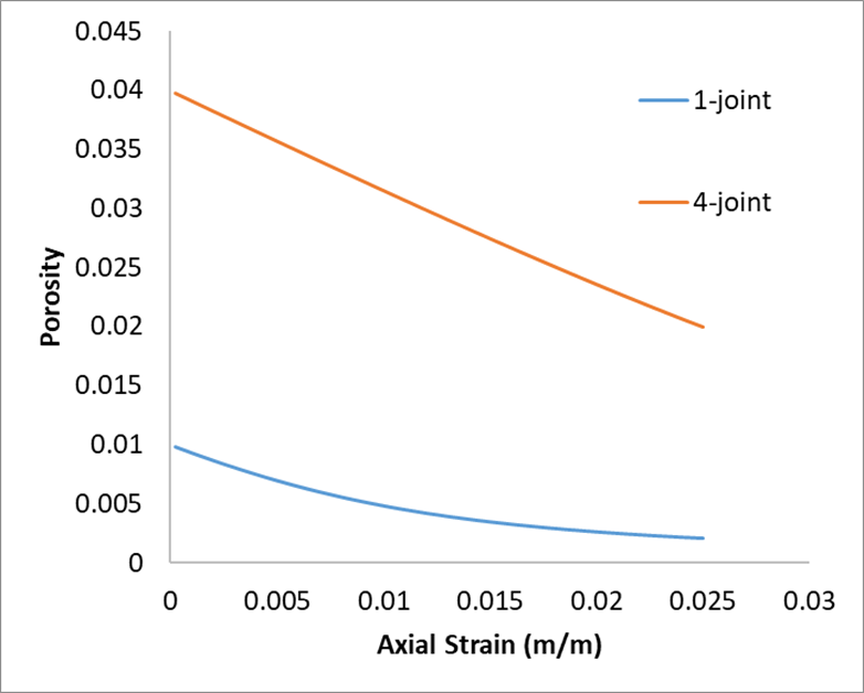
The result files for this example is available in directory: fract_003\Results. These results are compared with Case01 which contains only 1 embedded joint. Figure 2 shows the element with 4 embedded joints exhibits even lower tangent modulus in the fracture closure stage due to higher fracture compliance accumulated from all 4 joints. The presence of multiple joints results in lower overall fracture stiffness (Figure 3), and thus the total joint normal displacement is higher in the 4-joint element (Figure 4). This can be explained by the inverse relationship between joint displacement and fracture stiffness, provided that the prescribed load is constant. It should be noted that higher value of total joint normal displacement does not imply higher individual joint normal displacement compared to the 1-joint model. This is observed in Figure 4. In terms of porosity, 4-joint element has higher initial value due to higher number of joints (Figure 5). The porosity reduces linearly due to linear reduction of total joint normal displacement. The reduction is around 50% from 0.04.
Although not shown here, the following results do not change when smaller (finer) elements were used.
|

