Step04 Restoration
The data files for restoration simulation are in: Geol_002b\Case02\04_Restoration\Data. Those files are:
1.Geol_002b_Case02_rest.dat main datafile for the restoration simulation. The data relevant to usage spatial distribution of facies is discussed in detail below.
2.Geol_002b_Case02_geom.geometry datafile with the group data read via the data structure Include. This is carried from the previous workflow step where the groups were renumbered. Further edits are made to assign materials to each layer and consider the same hourglass properties as in Case01. Hence those edits are not discussed in detail here.
3.Geol_002b_Case02_geomB.dat datafile generated during the previous workflow step containing the Geometry_set data required to apply the couple freedoms constrain. This is read via the keyword Include defined in the main data file.
4.Geol_002b_Case02_geomB.geo geometry for the model.
5.Geol_002b_Case02_rest_geostatic.dat containing the geostatic data and compaction curves defining the initial porosities and the decompaction curves for each Facies to be used during restoration. This will be discussed in detail below.
6.Geol_002b_Case02_RestSurf01.dat datafile containing the restoration surface.
7.Geol_002b_rest01_Ss_Si_Sh_Ca.mat material datafile containing the materials used in the simulation.
8.Geol_002b_Case02_properties_ReNum.spat file containing the facies grid to be assigned to the model mesh.
What follows is a description of the data relevant to usage of Facies in both Geol_002b_Case02_rest.dat and Geol_002b_Case02_rest_geostatic.dat datafiles.
Facies definition
The assignment of facies to each element and the assignment of material properties to each Facies is performed in the main restoration data file (Geol_002b_Case02_rest.dat) and is described below.
|
Geostatic initialisation
The different facies are initialised using different porosity vs. depth curves. This is described below.
|
Output of Facies grid
At the end of each restoration stage a Spatial_grid with the Facies ID numbers distribution for the formation / group being back stripped needs to be output in order to allow the corresponding facies assignment during sedimentation in the forward simulation. The required data is described below.
|
Results
The results for the present workflow steps are provided in Geol_002b\Case02\04_Restoration\Results. Note that only a selection of the results are provided.
From restoration the following spatial grid files to constrain the forward model have been exported:
•Geol_002b_Case02_rest_Disp_formationNN.spat a spatial grid containing the boundary displacements for the forward model after deposition of each formation •Geol_002b_Case02_rest_Fac_formationNN.spat a spatial grid containing the facies ID number distribution for each deposited layer
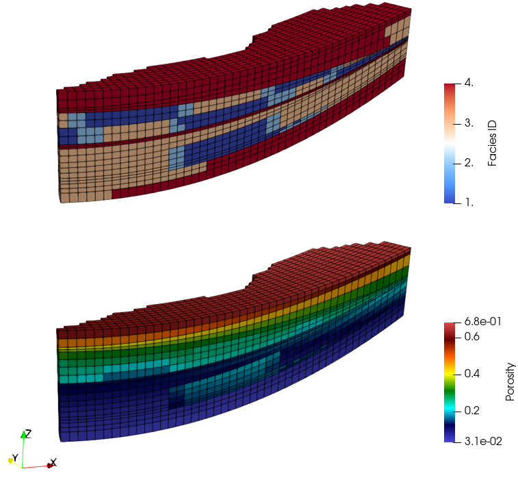
Loading the file Geol_002b_Case02_rest.xmf in ParaView the full series of plot files (.plt) at all output times can be visualised. As can be seen in the picture below the facies distribution has been applied to the model according to the facies grid, as well as the initial porosity, which uses a different compaction trend for each facies.
Initial Facies and porosity distribution after geostatic stage in the model. V.E.=3
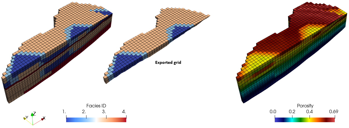
In the figure below the facies and porosity distribution at the end of formation08 stage are shown. At the end of such stage the spatial grid with the facies distribution for formation08 has been exported to the Geol_002b_Case02_rest_Fac_formation08.spat file. The exported spatial grids (both displacement and facies distribution) can be visualised by loading the Geol_002b_Case02_rest_sgd_NN.xmf in ParaView which loads the results from the corresponding NNth .sgd file where NN is the simulation stage number.
Facies distribution, exported facies grid and porosity distribution at the end of the 4th simulation stage (translate of formation08)
|


