Mech_003 Rift Sandbox Simulation using Prescribed Boundary Data
This example provides an introduction to using part-geometry and prescribed boundary data to define the deformation of an external surface of a model. Specific issues considered in this example are:
1Defining geometry parts.
2Assignment of boundary surface data.
Several advanced procedures are used including;
1Stratigraphy definition
2Adaptive mesh refinement
3Material grids
4Layer Sedimentation
The documentation assumes that the following examples have been undertaken beforehand:
1Mesh_001 2-D Unstructured Mesh Generation
2Mech_001 Mechanical Analysis Introduction
3Mech_004 Biaxial Test on Sand with Adaptive Remeshing
The Part_geometry_set data structure defines a geometry set; e.g. a group of lines or surfaces, that does not form part of the simulation domain. Part_geometry_set's are used to define boundary conditions e.g. Prescribed_boundary_data. The geometry is defined in terms of lines (Part_line) in 2-D and surfaces (Part_surface) in 3-D. It is important that standard geometry lines (Geometry_line) and surfaces (Geometry_surface) are not used to define Part_geometry_set's. Part geometry is faceted so that Part_line is defined as faceted polyline and Part_surface is a tessellated surface. Part geometry is unaffected by remeshing operations.
Part geometry is defined as a single or series of Part_geometry_set's, with each set requiring: 1A list of part-geometry entities in the set. 2The definition of each geometry entity i.e. Part_line's or Part_surface's. 3The nodal coordinates of the nodes defining the geometry entities in the set Part_nodal_data ISET. Optionally the part-geometry may be assigned a deformation by defining a list of updated coordinates, via Part_nodal_update together with a Time_curve.
Part-Geometry Defined as a Single Part_line with coordinates updated using Part_nodal_update
|
The Prescribed_boundary_data structure defines a special prescribed displacement boundary condition defined using either a Lagrangian or Eulerian description.
Lagrangian Description The geometry of the model is prescribed to be located on a rigid boundary surface; e.g. the basement geometry. The advantage of this load type is that the rigid boundary surface may be assigned a prescribed movement corresponding the evolution of the sediment outside the model; e.g. differential uplift, fault offset, etc. This type of differential displacement would be difficult to apply directly to the model due to the continuous remeshing that is used to accommodate the large deformations.
Eulerian Description With the Eulerian prescribed boundary the mesh is free to move relative to the boundary surface and material is continuously added or removed to the model so the model domain is consistent with the boundary surface geometry. This option is used for example to define sedimentation or erosion processes in a geomechanical analysis.
By default a Lagrangian boundary description is used and the primary data required is 1The geometry entities in the model to be assigned to the boundary. These are geometry lines in 2-D and geometry surfaces in 3-D. 2The part-geometry set to be used 3The time curve associated with the update of the part-geometry is the prescribed boundary is moving during the simulation.
The Prescribed Boundary is Defined by Assigning Part-Geometry Set 1 to Lines L1 and L2
Sandbox Simulation with Extension and Vertical Offset of a Boundary Surface
|
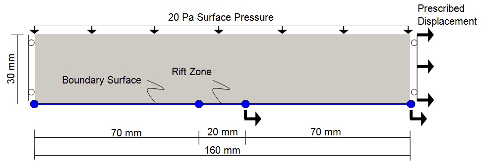
The problem consists of a 160mm long by 30mm high sand sample that is subjected to basal stretching in the central section to promote rifting. The side walls of the sample are constrained in the X-direction and an applied displacement is applied to the right hand boundary. A prescribed boundary surface is assigned to the base of the model. The topology of the boundary surface is defined by a part-geometry; which denotes geometry entities that does not form part of the model geometry; i.e. they are never meshed. The part-geometry is assigned differential movement that results in stretch of the central section of the model. An initial stage is performed where gravity is activated using an S-Curve time curve prior to initiating the stretching phase in stage 2.
The material corresponds to "sand_1" in the "training.mdb" material database, The model is elastoplastic with linear elasticity. The main properties for this material are:
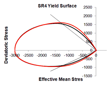
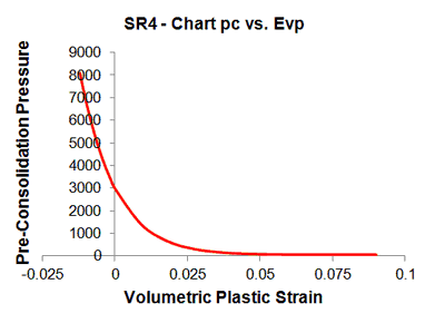
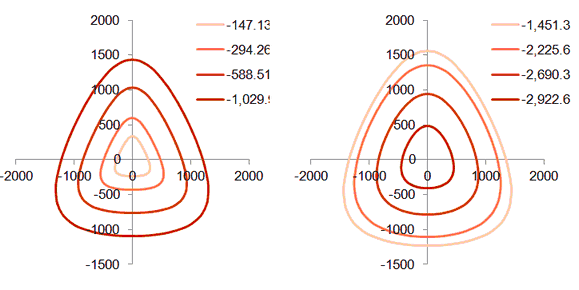
The shape of the initial yield surface in the p-q plane, hardening evolution of pc vs epv and the shape of the initial yield surface in the deviatoric plane are shown below.
|
Simulation Cases
Three Cases are considered with a full description of part-geometry and prescribed boundaries provided in Case 1 Extension via a Prescribed Boundary.
Case 1 Extension via a Prescribed Boundary
Case 2 Extension with Rapid Sedimentation Rate
Case 3 Extension with Slow Sedimentation Rate


