Case 1 Extension via a Prescribed Boundary
| Basic Set Up: Data File Description |
The initial data file for the project is: mech_003\Data\mech_003_Case1.dat. The basic data includes: 1Stratigraphy definition for one stratigraphy unit for group "Sand" and the corresponding surface horizon defined by geometry line 3 (see Mech_004 for description). 2A single group which is assigned the "Sand_1" properties defined using Group_control_data and Group_data data structures. 3Material properties (Material_data) exported from material database training.mdb. 4Time scaling data (Time_scaling_data) with target time step 1E-4s. 5Support data (Support_data) defining line 1 and line 3 as fully fixed. 6Load Case data (Global_loads and Load_case_control_data) for two load cases: (a) Load Case 1 - Prescribed displacement of the top surface of the specimen (b) Load Case 2 - the surface load corresponding to the confining pressure 7Gravity data (Gravity_data). 8Mesh control (Mesh_control) and Unstructured mesh generation data (Unstructured_mesh_data) defining a constant mesh size of 1.5mm. 9Control data (Control_data) defining: (a) Transient solution algorithm (Type 1) (b) Termination time of t=1.0s (c) Factor of critical time step = 0.5 i.e. lower than the default value (d) Plot file output every 0.05s
|
The Part_geometry_set data structure defines a geometry set; e.g. a group of lines or surfaces, that does not form part of the simulation domain. For the current case, a single part-geometry set (Set=1) is defined that corresponds to the base of the sandbox. This is defined by a single Part_line with three facets and four nodes.
Geometry Description for Part_line 1
The coordinates in the initial configuration, defined via Part_nodal_data (Set=1), are:
Initial Nodal Coordinates for Part Geometry Set 1
The location of these nodes is updated by specifying Part_nodal_upate (Set=1) to coordinates
Update Nodal Coordinates for Part Geometry Set 1
This stretches the central facet on the part geometry from 20mm length to 40mm length.
|
| Results |
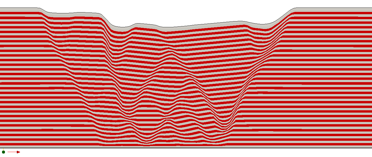
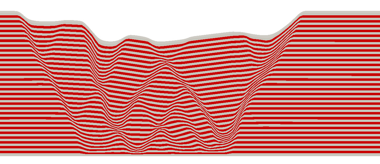
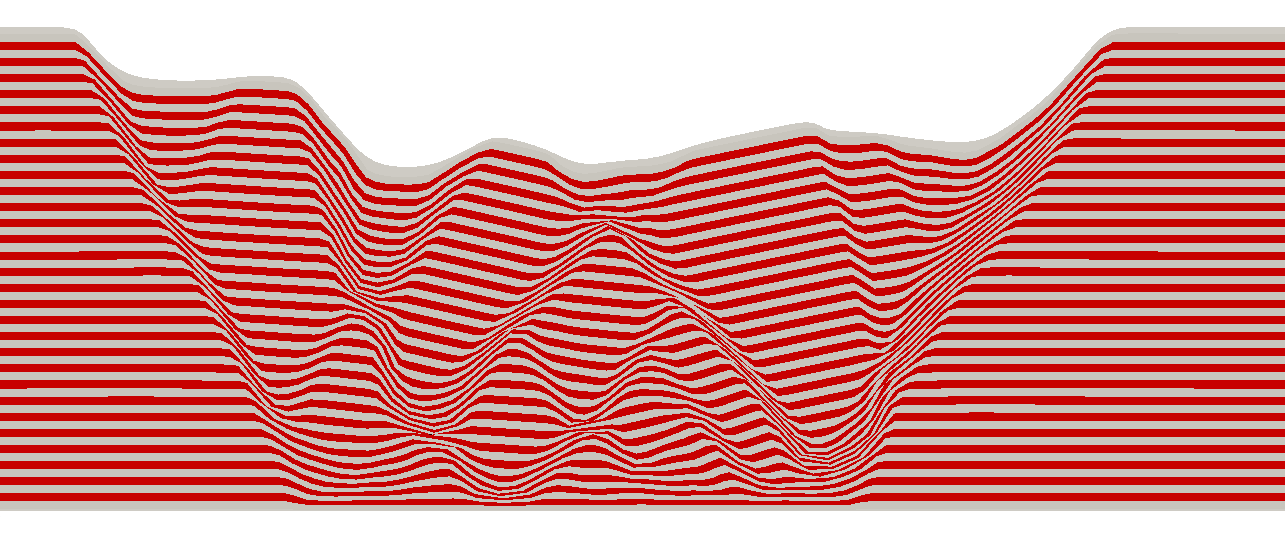
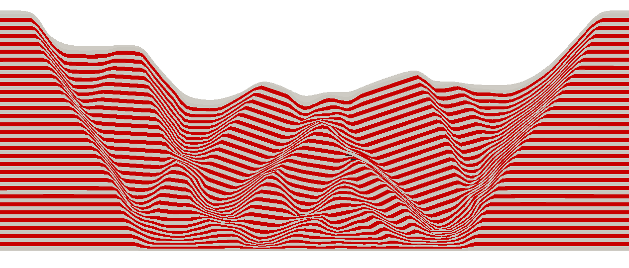
The result files for the project are in directory: mech_003\Case 1\results. The contour plots of plastic strain and deformation of the material grid show that the majority of the deformation occurs in the sand above the stretched boundary facet and that the material near the left and right hand boundaries remains elastic. The basement stretch results in a rift type structure with complex faulted geometry.
Contours of Plastic Strain at Time t=6.0
Configuration of Material Grid at Time t=3.0
Configuration of Material Grid at Time t=4.0
Configuration of Material Grid at Time t=5.0
Configuration of Material Grid at Time t=6.0
|


