Case 1 Basic Set Up for Adaptive Remeshing
The initial data file for the project is: mech_004\Data\mech_004_Case1.dat. The basic data includes:
1A single group which is assigned the "Sand_1" properties defined using Group_control_data and Group_data data structures.
2Material properties (Material_data) exported from material database training.mdb.
3Time scaling data (Time_scaling_data) with target time step 1E-4s.
4Support data (Support_data) defining line 1 and line 3 as fully fixed.
5Mesh control (Mesh_control) and Unstructured mesh generation data (Unstructured_mesh_data) defining a constant mesh size of 1.5mm.
6Control data (Control_data) defining:
(a) Transient solution algorithm (Type 1),
(b) Termination time of t=1.0s,
(c) Factor of critical time step = 0.5 i.e. lower than the default value,
(d) Plot file output every 0.05s,
Two load cases are defined •Load Case 1 - Prescribed displacement of the top surface of the specimen •Load Case 2 - the surface load corresponding to the confining pressure
Load Case 1 - Prescribed Displacement
Load Case 2 - Initial Conditions and Confining Pressure
|
The Adaptivity_control_data data structure identifies that adaptive remeshing is to be used and defines the key control data. Compulsory data comprises: 1The error evaluation frequency (Error_evaluation_frequency); i.e. the number of steps between each remeshing error check. 2The default maximum and minimum element sizes (Default_element_sizes). These values may be overwritten by maximum and minimum element sizes specified in adaptivity set data (Adaptivity_set_data). 3A list of remeshing sets (List_of_remesh_sets). The remeshing sets specify additional data for error estimation and the target element size on the new mesh. At least one remeshing set (Adaptivity_set_data), generally defining data for the complete domain, must be specified. Several additional data items may be defined including the Maximum_remesh_frequency, which defines the maximum number of error evaluation checks before a remesh must be performed.
|
Adaptivity_set_data data structures are used to define additional data to control the error estimation and target element size either for the whole domain or specific regions of the domain. In this case the most basic definition is applied to the complete domain; i.e. the two compulsory values: 1A distortion error value for triggering a remesh operation - the error trigger based on area change is used. 2Maximum and minimum element sizes for elements in the adaptivity set. These values overwrite the default values provided in the Adaptivity_control_data data structure.
|
Material grids are uniform grids that can be superimposed on the finite element mesh. Once active, the grid deforms with the mesh and therefore gives an indication of the distortion of the model. They are particularly useful in visualisation of localised deformation; i.e. shear bands and faults. They are often defined in the initial configuration but can also be defined part the way through an analysis; i.e. when new material is sedimented. The compulsory data for Material_grid_set comprises: 1A list of groups, specified by name (Group_names) or number (Groups), for which material grids should be generated. An individual grid is generated for each group. 2The division size (cell size) for the group. The division size in the x-direction (Division_size_x) must be specified and by default the division size in the Y-direction is identical. 3The grid origin (Grid_origin) - which in 2-D the X and Y coordinates of the lower left hand corner of the grid.
Contour values that define stripes when post-processed may also be output, via Stripe_spacing_x and Stripe_spacing_y. These provide an effective visualisation option that may be displayed with or without the underlying grid in ParaView. Material grids can be visualized by loading the grid plot file filename_grid.xmf
|
| Results |
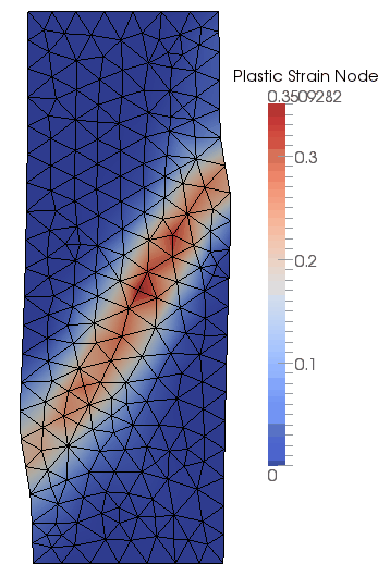
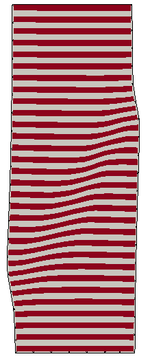
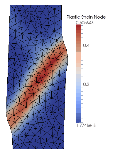
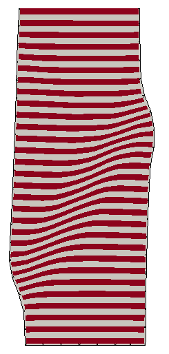
The result files for the project are in directory: mech_004\exercises\Case 1\results. The contour plots of plastic strain and deformation of the material grid show that the majority of the deformation occurs in a left dipping shear band, with less intense shearing on a second right dipping shear band in the top section of the specimen. Due to the coarse mesh adopted in the simulation the shear band is quite broad and diffuse, as there is insufficient kinematic freedom in the mesh to deform in a narrow band.
Configuration at Time t=0.5s
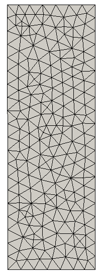
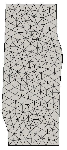
Configuration at Time t=1.0s The mesh in the initial and final configuration show that the element size has remained relatively constant and that, although the specimen is highly deformed, adaptive remeshing has resulted in an mesh without large element distortions. Eleven remeshing steps were performed in the simulation.
Mesh in Initial and Final Configuration
|

