Case06 Reservoir with Embedded Fractures
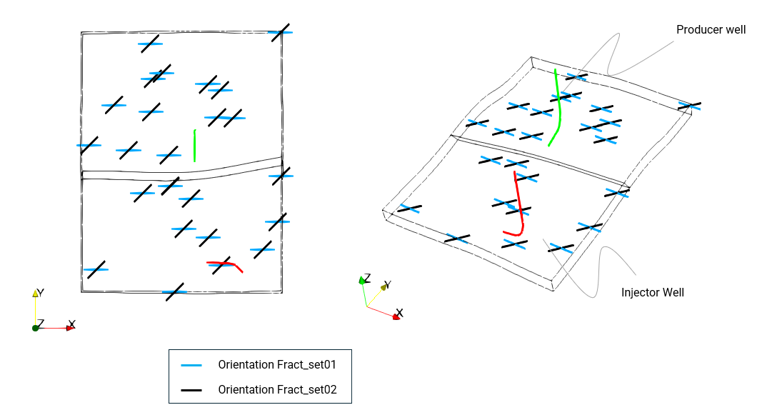
In the present tutorial example the effect of fractures in the permeability and flow field will be considered. To this end the embedded fracture approach will be adopted. Two fracture sets with different orientations will be defined within the reservoir formation. Both fracture sets consider vertical fractures; Fract_set01 aligned with the XZ plane and the second oriented 45 degrees relative to the XZ and YZ planes.

View of the reservoir (formation04) showing fracture directions for the two fracture sets
Two cases are considered:
▪Case06a: Ubiquitous fractures with homogeneous properties within the reservoir and fracture spacing of 5m.
▪Case06b: Two corridors of fractures within the reservoir with spatial definition of fracture spacing ranging from 25m to 75m.
The data files for the project are in: MEM_001\Case06\Data. The main data file, contact and matrix material properties are identical to the Case04 example. Thus the files provided which are identical will be named with "_Case04_" in the file names whereas the files that are changed for the present cases will include "_Case06" in the names:
Files with data exclusive / modified for the present cases:
▪MEM_001_Case06a.dat and MEM_001_Case06b.dat: Main data files for the simulations
▪MEM_001_Case06.mat: Material file containing definition of materials for the different formations as well as the definition of fractures
▪MEM_001_Case06_FSetXX_Act.spat: File containing the spatial grid definition for the Activation Flag for Fracture set XX
▪MEM_001_Case06_FSetXX_Spacing.spat: File containing the spatial grid definition for the Fracture Spacing for Fracture set XX
▪Direction_Cosines.xls: Excel sheet used to obtain the direction cosines for the coordinate systems defining the orientation of the fractures
▪Grid_Definition.xlsx: Excel sheet used to generate the spatial properties in Case06b (not required but provided for reference)
Files with data identical to Case04 example:
▪MEM_001_Case04_Fine_mesh.geo: File containing the meshed geometry
▪MEM_001_Case04.contact: File containing the contact data
▪MEM_001_Case04.geometry: File containing definition of Group_data and Geometry_set data
▪MEM_001_Case04_node_PP_Initial.spat: File containing the spatial grid defining the values of the initial pore pressure values at each node
▪MEM_001_Case04_Porosity.spat: File containing the spatial grid defining the values of the initial porosity values at each element
▪geostatic.set: Set file containing definition of the different sets of Geostatic_control_data
The following describes only the data relative to the definition of fractures.
Case06a and Case06b
For both cases the material file is identical. This contains the definitions and assignments relevant to the 2 fractures sets.
Material Data File (MEM_001_Case06.mat) |
|
* Material_data ! ---------------------------------------- Material_name "Reservoir"
(...) ! ------------------------------------------------- Permeability 1E-12 ! ------------------------------------------------- Fracture_set_names IDM=2 "Fract_set01" "Fract_set02"
* Fracture_data NUM=1 ! ----------------------------------------- Name "Fract_set01" Fracture_type "PreExist" Coordinate_system_name "Set01" Fracture_spacing 5.0 Conductivity_model "PermMult" Permeability_multiplier 5.0
* Fracture_data NUM=2 ! ----------------------------------------- Name "Fract_set02" Fracture_type "PreExist" Coordinate_system_name "Set02" Fracture_spacing 5.0 Conductivity_model "PermCons" Permeability 5E-12
* Coordinate_system NUM=1 ! ----------------------------------------- Name "Set01" Direction_cosines IDM=3 JDM=3 1.0000000000 0.0000000000 0.0000000000 0.0000000000 0.0000000000 -1.0000000000 0.0000000000 1.0000000000 0.0000000000
* Coordinate_system NUM=2 ! ----------------------------------------- Name "Set02" Direction_cosines IDM=3 JDM=3 0.7071067812 0.7071067812 0.0000000000 0.0000000000 0.0000000000 -1.0000000000 -0.7071067812 0.7071067812 0.0000000000
|
1.For both cases the definitions of the fractures are identical.
2.Two fracture sets are defined via Fracture_data data structures and are assigned by name to the "Reservoir" material via the Fracture_set_names keyword. Note that the properties for both fracture sets are identical (spacing and permeability) but two different permeability models via the Conductivity_model keyword are used to define the same fracture permeability value for demonstration purposes:
i.PermCons defines the constant absolute fracture permeability via the Permeability keyword.
ii.PermMult defines the fracture permeability as a multiplier of the matrix permeability via the Permeability_multiplier keyword.
3.Fracture_spacing is set to 5.0 m.
4.Each fracture set has its corresponding Coordinate_system assigned via the Coordinate_system_name keyword. These coordinate systems define the fracture orientation which is normal to the Z axis of each coordinate system. Hence "Set01" defines a coordinate system rotated 90 degrees along the X axis, and "Set02" defines a coordinate system rotated 90 degrees along the X axis followed by a 45 degrees rotation along the new / local Y axis (which is aligned with the Z global axis after the initial rotation of 90 degrees along the X axis).
|
Case06b Spatial distribution of fracture properties
Case06b has additional data relative to Case06a in order to consider a spatial distribution of fracture properties. These spatial properties consist of:
•Act_flag : Fracture activation flag to define the presence of fractures only in the regions where Act_flag = 1
•F_space : Defining the fracture spacing (which will overwrite the default value specified within Fracture_data)
The spatial properties are defined via a Spatial_grid data structure containing the values in each grid cell for each property in each fracture set. In the present case regular spatial grids (pillar grids) with equally sized cells in each direction (Type set as Grid1) are used, but any type of Spatial_grid may be used to map property values from the spatial grid to the model mesh.
The values from the spatial grids are mapped to the model mesh via the Spatial_state_set data structures.
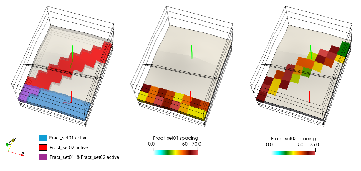
The activation flag for each of the fracture sets define a corridor of active fractures each of which has approximately the same orientation as its corresponding fracture set. Values for fracture spacing are defined in all grid cells (covering the whole reservoir) but only those elements that contain active fractures will be displayed in ParaView.

View of the location of active fractures for each fracture set and their corresponding fracture spacing values
The following describes a typical Spatial_grid and its corresponding Spatial_state_set. Similar definitions are used for each of the properties in each of the fracture sets.
MEM_001_Case06b_FSet01_Spacing.spat |
|
* Spatial_grid NUM=3 ! ---------------------------------------- Name "FSet01_Spa" Type "Grid1" Num_cells_X 8 Num_cells_Y 11 Num_cells_Z 1 Cell_division_X 1000.0 Cell_division_Y 1000.0 Cell_division_Z 10000.0 Grid_origin IDM=3 0.0 0.0 0.0 Cell_variables IDM=1 "F_space" Cell_values IDM=1 JDM=88 35 45 70 55 70 40 35 35 60 45 55 50 35 45 55 50 . . . 75 75 25 35 65 70 40 35
|
1.The Name of the spatial grid is defined as "FSet01_Spa".
2.The Type of grid is defined as Grid1; a regular pillar grid with the constant cell size in each direction defined by:
i.Location of the Grid_origin (in the present case [x, y, z] = [0, 0, 0] ).
ii.Number of cells in each direction (Num_cells_X, Num_cells_Y and Num_cells_Z).
iii.Cell size in each direction (Cell_division_X, Cell_division_Y and Cell_division_Z ) defining cells of 1000 m x 1000 m x 10000 m.
3.In the present case the property values are defined at grid cells via:
i.Cell_variables specifying the name of the properties being defined in the present grid which in this case consist of a single variable "F_space" (fracture spacing).
ii.Cell_values defining the value of the properties at each cell.
|
MEM_001_Case06b.dat |
|
* Include ! --------------------------------- Filename MEM_001_Case06b_FSet01_Spacing.spat
* Spatial_state_set NUM=3 ! --------------------------------- Spatial_grid "FSet01_Spa" Groups IDM=1 "Formation04" Fracture_set "Fract_set01" Fracture_variables IDM=1 "F_space"
|
1.An Include data structure is used to read each of the .spat files containing the spatial grids.
2.A Spatial_state_set data structure is used to assign/map the values defined in each spatial grid to the elements in the mesh. Each Spatial_state_set requires definition of:
i.The spatial grid name via the Spatial_grid keyword.
ii.The list of Groups to which the values are going to be mapped to.
iii. The name of the Fracture_set for which we are going to assign values.
iv.The name of all Fracture_variables for which we are going to map the values.
|
Results
The results for the example are located in MEM_001\Case06\Results. Only the last plot file for each case is provided.
The plot file for each case may be visualized in ParaView by loading the corresponding .xmf file (e.g. MEM_001_Case06a_028.xmf).
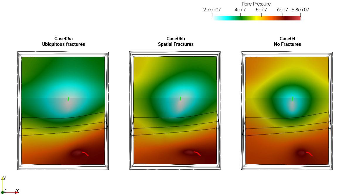
The pore pressure contours plotted below show the effect of fractures in the pressure distribution:
i.For both cases with fractures (Case06a and 06b), the colors in each extreme of the color range occupy a larger surface area around the wells compared to the no fracture Case04 due to the effect of the enhanced perm attributed to the presence of fractures.
ii.Case06a has more surface area covered by the colours in the extremes of the color range than Case06b as: a.Fractures in both fracture sets are ubiquitous in Case06a and hence the fluid has more freedom to flow b.There are more fractures per element in Case06a (spacing of 5m) than in Case06b (spacing ranging from 25m to 75m)
iii.The contours in Case06b show a certain degree of alignment with the orientation of the active fracture set around each of the wells; i.e. note the ellipsoid shapes of the bound range colors, showing approximately an orientation of 45º relative to the X axis around the producer well (green line) and an alignment with the X axis near the injector well (red line).
Pore pressure contours at the end of simulation (t=105) for Cases 06a, 06b and 04
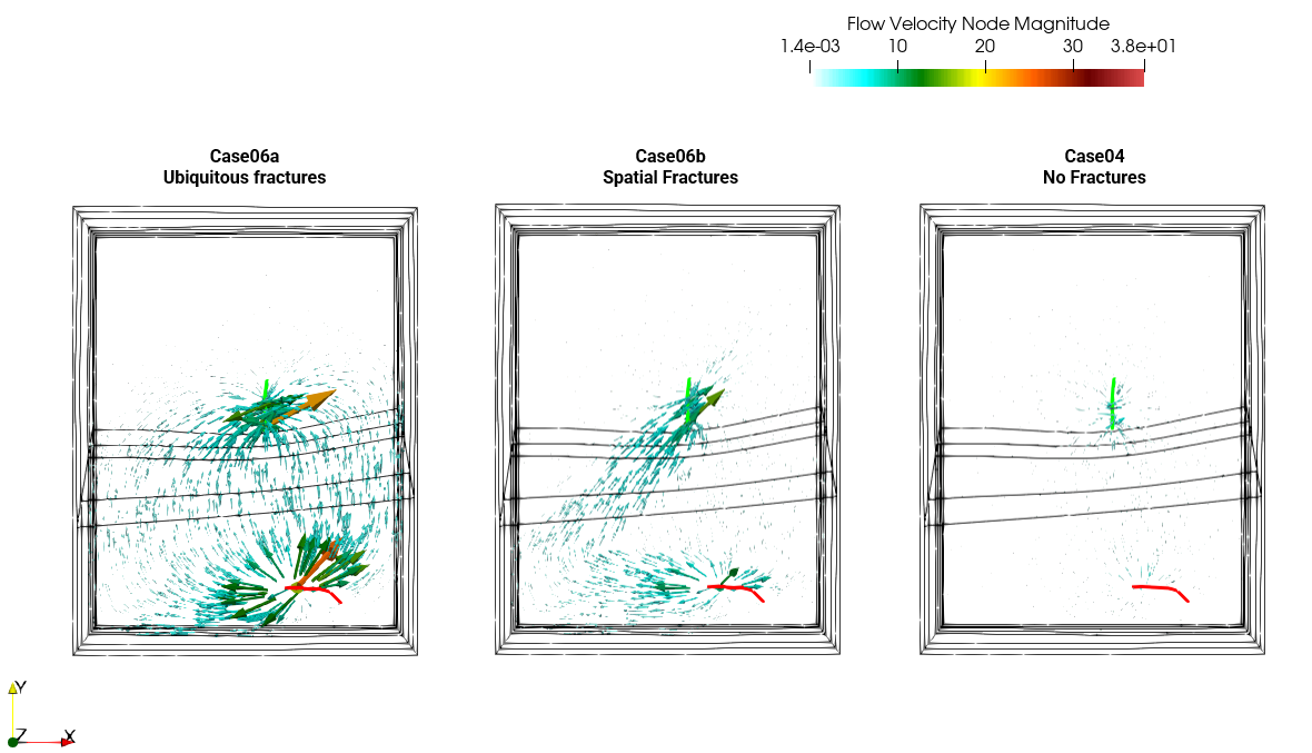
The plot below shows the flow velocity vectors plotted for each case. These plots also show the effect of the presence of fractures in the solution; i.e.:
i.Both cases with fractures (Case06a and 06b) show larger flow velocities than the no fracture Case04.
ii.Case06b shows clear preferential pathways aligned with the fracture corridors and fracture orientations.
iii.Case06a shows larger flow velocities than Case06b due to the fact that in Case06a the fractures are ubiquitous and it has a larger fracture count per element relative to Case06b (due to the smaller fracture spacing).
Flow velocity vectors at the end of simulation (t=105) for Cases 06a, 06b and 04. Note that the flow velocity glyph for all cases has been plotted for 1 every 30 elements with a scaling factor of 100.
|


