MEM_003 Boundary Optimisation and Super Element
In the present tutorial example the model defined previously in MEM_001 tutorial example will be used to demonstrate the set up for performing boundary condition optimization within the MEM initialisation workflow in ParaGeo. Boundary optimization procedure uses ParaGeoInv framework to perform inverse analysis and find the optimal boundary conditions that are consistent with target observations at defined history points within the model domain. (For more information on ParaGeoInv and inverse analysis see ParaGeoInv Reference Manual. Undertaking of GeoInv Tutorial Examples prior to the present example is also recommended).
Because during an inverse analysis numerous simulations are performed, the procedure will benefit from using the super element approach in order to decrease the number of freedoms in the solution and hence save CPU time (see SuEl_001 tutorial example). Hence a case including usage of the super element will also be considered.
Note that in the present example only the first two initialization stages will be performed which correspond to gravity initialisation and tectonic displacement respectively, the tectonic displacement magnitude being the parameter to be optimized. The optimization will be performed using stress values measured at 9 point locations as a target. The target includes stresses in x, y and z directions. Details on the locations of the points is provided below.
The reference solution (with tectonic displacement of -25.0 on the north boundary) used to generate the target measurements is also provided to allow for comparisons. The data and results are in MEM_003\Reference Solution.
Geometry Description
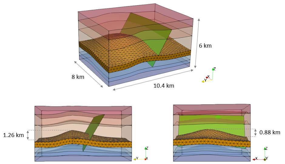
The model geometry is 8 km x 10.4 km x 6 km containing 7 formations which are assigned names Formation01 to Formation07 from oldest to youngest formation and where Formation04 is a Reservoir. The main structure consists in a two way anticline with a fault intersecting the southern limb. The top of the reservoir in the anticline crest is at c.a. 2.6 Km depth and it has a maximum relief of 1.26 km in the North-South direction and a maximum relief of 0.88 km in the East-West direction.

Model geometry from different perspectives
Target
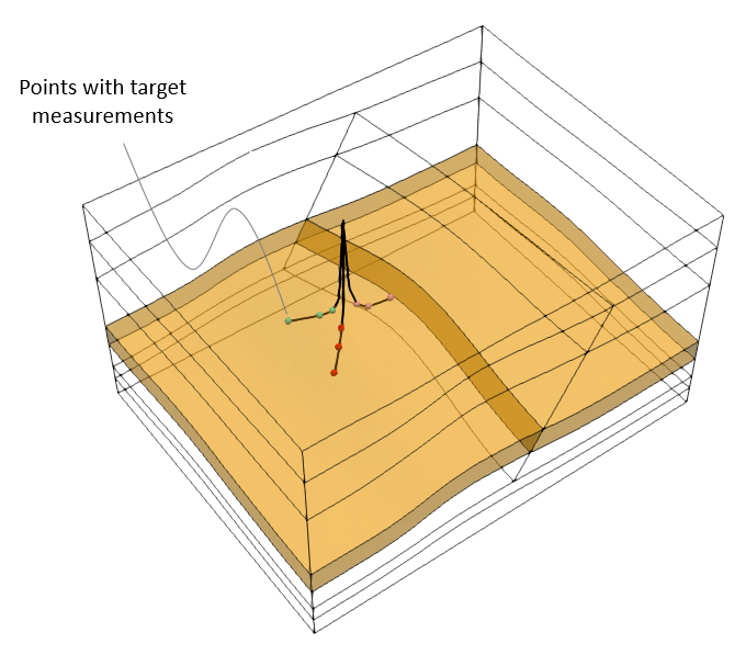
The target measurements used to perform the optimization procedure consist of stresses in X, Y and Z directions at 9 point locations within the reservoir. Those point locations are indicated in the picture below and as can be seen they correspond to points used to define the three notional well paths specified in MEM_001 tutorial example.

Model geometry with indication of the points with target measurements
Simulation Cases
Case02 Boundary optimisation using the super element (currently unavailable)
