Case01 Mesh size defined on geometry entities


In the present case the method for defining mesh element sizes on geometry entities is shown. The following files are provided in Mesh_002\Case01\Data :


Mesh_002_Case01a.dat : mesh generation with a default element size of 120 m and a smaller mesh size to two surfaces

Mesh_002_Case01b.dat : mesh generation with a default element size of 120 m and a smaller mesh size to two surfaces and the lines that define those two surfaces


Below a description of the data files is provided. It should be noted that only the data relative to mesh generation will be described in detail while for the remaining data a brief description is provided.


Datafile Description


The basic data includes:


1.Geometry definition data (Nodal_data , Geometry_line , Geometry_surface and Geometry_volume ) at the end of the file after the END DATA command to define the cube geometry.

2.Group_data and Group_control_data for a single group with TET4V elements (note that the Element_type defined must be valid for the type of mesh being generated)

3.Material_data and Fluid_properties defining an elastic material

4.Support_data defining displacement fixities in the 3 directions for the whole cube volume (by assigning the corresponding Displacement_codes set to the internal Geometry_set "All_volumes" )

5.Mesh generation data (Mesh_control_data and Unstructured_mesh_data ) with the appropiate data for each case

6.Control_data defining the Duration of the simulation stage, the Target_number_time_steps for the stage as well as several output options.


Case01a Mesh Generation Data


Data File


* Mesh_control_data

! ---------------------------------

 Generation_algorithm    2          

 Mesh_generation_flag    0


* Unstructured_mesh_data

! ---------------------------------

 Default_element_size         120.0

 Element_size_bounds IDM=2

  /Max. Element Size/        120.0

  /Min. Element Size/         30.0

 Surfaces  IDM=2

   2   3

 Surface_element_size  IDM=2

   30  60


1.Mesh_control_data defines the options for mesh generation. In this case this has been set to:

a.Generation_algorithm is set to 2 (unstructured mesh)

b.Mesh_generation_flag is set to 0 in order to perform the analysis. Note that in this case it would not be required as we are only interested in generating the mesh.


2.Unstructured_mesh_data defines:

a.A default element size of 120 m.

b.Maximum and minimum mesh size bounds set to 120.0 m and 30.0 m respectively

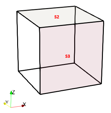
c.Mesh size of 30 m and 60 m to surfaces 2 and 3 respectively, defined via Surfaces and Surface_element_size keywords. See the figure below for reference.


Mesh_002_Fig02

Geometry with surfaces with specific mesh data highlighted


Case01b Mesh Generation Data


Data File


* Mesh_control_data

! ---------------------------------

 Generation_algorithm    2          

 Mesh_generation_flag    0


* Unstructured_mesh_data

! ---------------------------------

 Default_element_size         120.0

 Element_size_bounds IDM=2

  /Max. Element Size/        120.0

  /Min. Element Size/        30.0

 Lines  IDM=7

   5  6  7  8         9  10  1

 Line_element_size  IDM=7

   30  30  30  30    60  60  60

 Surfaces  IDM=2

   2   3

 Surface_element_size  IDM=2

   30  60


1.Mesh_control_data defines the options for mesh generation. In this case this has been set to:

a.Generation_algorithm is set to 2 (unstructured mesh)

b.Mesh_generation_flag is set to 0 in order to perform the analysis. Note that in this case it would not be required as we are only interested in generating the mesh.


2.Unstructured_mesh_data defines:

a.A default element size of 120 m.

b.Maximum and minimum mesh size bounds set to 120.0 m and 30.0 m respectively

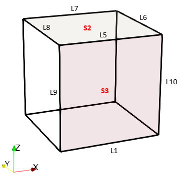
c.Mesh size of 30 m and 60 m to surfaces 2 and 3 respectively, defined via Surfaces and Surface_element_size keywords. See figure below for reference.

d.Lines that define the two previous surfaces are defined consistent element sizes as specified via Lines and Line_element_size keywords. See figure below for reference.


Mesh_002_Fig03

Geometry with surfaces and lines with specific mesh data highlighted


Results


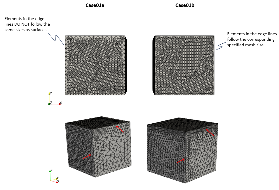
The results are provided in: Mesh_002\Case01\Results. As can be seen in the figure below in Case01a the elements in the edges do not have the same size as the adjacent surface. This is because the mesh is generated in an hierarchical manner where lines are discretized first, then surfaces and last volumes. In Case01b can be seen that the specified element sizes on the lines enforced the mesh size in those entities. Where two lines share a node the smaller size takes priority.


Mesh_002_Fig04

Results for the two cases