Case03 Usage of adaptivity
In the present case usage of adaptivity data to remesh the geometry in order to achieve a mesh with regions with different element sizes will be demonstrated. The advantage of using adaptivity is that on every remesh, the previous mesh is used as a background mesh and the target element sizes specified in the different adaptivity regions are prescribed on the background mesh nodes. Consequently it is more easy and convenient to achieve the desired mesh using adaptivity than attempting to achieve it in the initial mesh generation using the existing functionality. It is noted that it is recommended to split the mesh generation and simulation workflow steps in two different data files as explained in Case00.
Below a description of the data files is provided. It should be noted that only the data relative to adaptivity will be described in detail while for the remaining data a brief description is provided.
Datafile Description
The basic data includes:
1.Geometry definition data (Nodal_data , Geometry_line , Geometry_surface and Geometry_volume ) at the end of the file after the END DATA command to define the cube geometry. 2.Group_data and Group_control_data for a single group with TET4V elements (note that the Element_type defined must be valid for the type of mesh being generated) 3.Material_data and Fluid_properties defining an elastic material 4.Support_data defining displacement fixities in the 3 directions for the whole cube volume (by assigning the corresponding Displacement_codes set to the internal Geometry_set "All_volumes" ) 5.Mesh generation data (Mesh_control_data and Unstructured_mesh_data) defining the initial mesh. 6.Adaptivity data to perform several remeshes (Adaptivity_control_data and Adaptivity_set_data ) 7.Control_data defining the Duration of the simulation stage, the Target_number_time_steps for the stage as well as several output options. It is noted that in the present case the initial mesh generation and and the remeshes have been separated in two stages to demonstrate the differences in the mesh (but this is not required). 8.Util_write_geometry data defined after the last Control_data to export the generated mesh into a .geo file
Mesh Data
Adaptivity Data
Remeshing requires definition of Adaptivity_control_data and a minimum of one Adaptivity_set_data. Then remesh will occur every time the criteria for remeshing is satisfied which is based on a user-defined threshold of element area (2D) / volume (3D) distortion expressed as a percentage (via Distortion_area_data keyword within Adaptivity_set_data). Consequently the code needs to check whether or not the remeshing criteria is satisfied, and such check is performed every "n" mechanical / coupling steps as defined by the user using the keyword Error_evaluation_frequency within Adaptivity_control_data. Then the keyword Maximum_remesh_frequency may be set to enforce a remesh every "m" remeshing criteria checks independently on whether or not the criteria has been satisfied. Thus in this example the data will be defined so that:
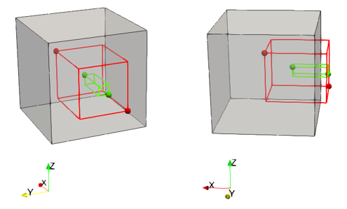
1.There will be 2 regions with smaller mesh sizes relative to the default element sizes outside of those regions 2.There will be 4 remeshes enforced during the simulation
|
| Results |
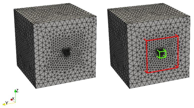
The results are provided in Mesh_002\Case03\Results. The file Mesh_002_Case03.xmf can be loaded in ParaView in order to visualize all the plot files from the simulation. As can be observed in the figure below a progressive decrease in the element size towards the center of the western geometry boundary is achieved as defined by the adaptivity data.
Results for the two cases with the mesh region in orange and the geometry points affected by the mesh region in green. The unaffected points are shown in grey
|


