The Step4 datafile contains data for simulation of the sub-model. The datafile is very similar to Step1 and Step2 datafiles. Only description of the key data and differences with Step1 are discussed in detail.
Data file for this exercise is located in directory: SubMod_001\Step4\Data. Look for text in the datafile and follow the instructions.
Basic Set Up: Data File Description
The initial data file for the project is: SubMod_001\Step4\Data\Submod_001_Step4.dat. The datafile is analogous to the Step1 datafile description with a few differences which are discussed bellow:
1Support_data is not used (displacements fully prescribed by the spatial grids). 2Global_loads and Load_case_control_data are not used (displacements fully prescribed by the spatial grids). 3Geometry data must be consistent with Step2 data (the created sub-model boundaries). 4A Include data structure is used to include the file with the displacement spatial grids. 5The Spatial_boundary data structure is used to prescribe the boundary conditions in each analysis stage. 6Mesh is defined with smaller element size.
Data File
|
|
* Include
Filename Submod_001_Step1_Disp.spat
|
1The "Submod_001_Step1_Disp.spat" file generated in Step3, which contains the spatial grids with the displacements in all boundaries is included. |
|
The Spatial_boundary data structure is used to prescribe the boundary conditions stored in the spatial grids generated in Step3 of the workflow. Note that this prescribed boundary condition is removed after each control stage, so that in order to continue prescribing the boundary condition associated with the spatial grid in the following stage analysis, Spatial_boundary data needs to be redefined.
Data File
|
|
* Spatial_boundary NUM=1
Name "sub_run"
File_name "Submod_001_Step1_Disp"
Boundary_type "Spatial_grid"
Conforming_mesh_flag 1
Spatial_grids IDM=6
"Base"
"West"
"East"
"Top_surface"
"South"
"North"
Prescribed_components IDM=3 JDM=6
1 2 3
1 2 3
1 2 3
1 2 3
1 2 3
1 2 3
|
1The "Submod_001_Step1_Disp.spat" file is assigned for prescribing boundary conditions data. 2Spatial grids are used to define the boundary conditions (boundary_type "Spatial_grid"). 3Mesh is set to conform at model boundaries (conforming_mesh_flag=1). 4All spatial grids for each of the model boundaries will be used to prescribe boundary conditions. 5The prescribed components for boundary conditions are DispX (1), DispY (2) and DispZ (3). Other possible components are Pore Pressure (4) and Temperature (5). |
|
A finer mesh compared to the large scale model is defined for the sub-model.
Data File
|
|
* Mesh_control_data
Generation_algorithm 2
Mesh_generation_flag 0
* Unstructured_mesh_data
Default_element_size 500
Element_size_bounds IDM=2
/Max. Element Size/ 500
/Min. Element Size/ 500
|
1The sub-model domain will be meshed with elements of 500 m in size.
|
|
Only the nodal_data is discussed here as Geometry_line, Geometry_surface and Geometry_volume data is identical to the one described in Example Step1.
Nodal_data
Data File
|
|
* nodal_data
node_number IDM=12
1 2 3 4 5 6 7 8 9 10
11 12
coordinates IDM=3 JDM=12
7500 1000 0
17500 1000 0
17500 1000 2500
17500 1000 3862.5
7500 1000 4512.5
7500 1000 2500
7500 10000 0
17500 10000 0
17500 10000 2500
17500 10000 3862.5
7500 10000 4512.5
7500 10000 2500
|
1The nodal data to define the sub-model is presented here (must be identical to the nodal data defined in Step2).
|
|
|
Results
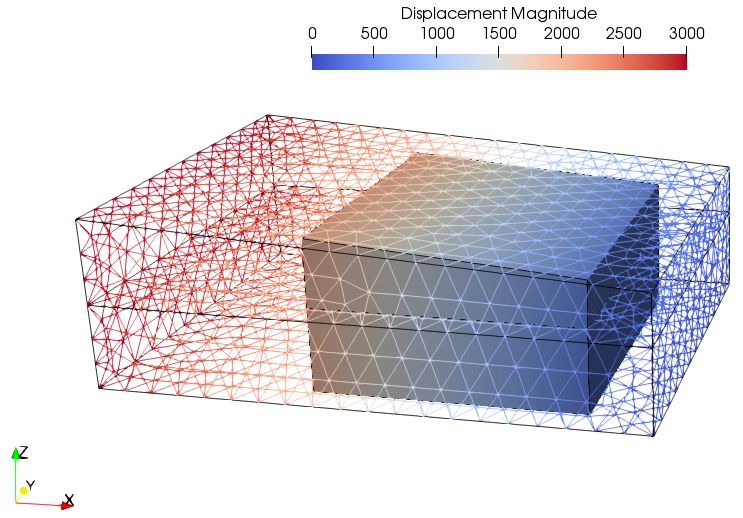
The result files for the project are in directory: Submod_001\Step 4\results. The displacement contour of the sub-model (solid surfaces) shows a perfect match with the displacement contours of the large scale model (wireframe).

Comparison of results at 0.5 Ma (after application of the displacements)
|

