Ex_012 Mapping 3D Grids in 2D Geometries
In this example the mapping of properties from a 3D grid to a 2D geometry will be demonstrated. For reference comparison, the mapping from the 3D grid to a 3D geometry example will also be provided. The facies distribution from the 3D grid are to be mapped to a 2D and 3D geometry comprising a normal fault with 8 formation layers. The files are provided in ParaGeo Examples\General Examples\Ex_012\Data and comprise:
•Ex_012_2d.dat and Ex_012_3d.dat : datafiles with minimal data required to perform the mapping of facies into the 2D and 3D geometries respectively.
•Ex_012_2d.geo and Ex_012_3d.geo : files containing the 2d and 3d meshed geometries
•Ex_012_2d.geometry and Ex_012_3d.geometry : group and geometry set data for the 2D and 3D cases respectively
•Ex_012_Facies.spat : file containing the 3d spatial grid with the facies distribution
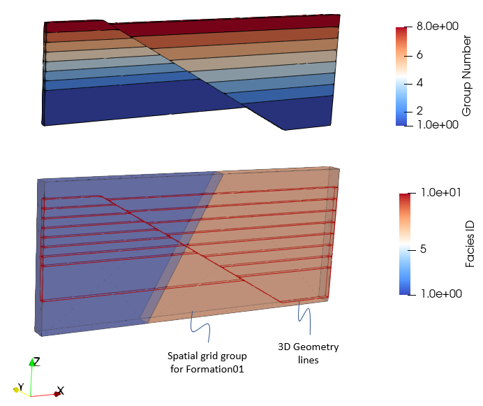
It should be noted that because the spatial grid was manually defined for this example its shape is unusual as it was done in the simplest way possible. Thus the spatial grid type is "group" with a rectangular prism defined by 2 HEX elements for each group (8 Spatial_grid_group data structures) , that bounds the full geometry with a diagonal boundary between the two HEX grid cells. A picture of the 3D geometry with the spatial grid group for Formation01 is provided for reference.

View of the 3D geometry and the spatial grid for formation 01 (each group has a grid defined with 2 HEX cells covering the entire geometry)
Each data file contains the minimal data to assign the facies distribution from the spatial grid to the corresponding geometry, namely:
•Geometry_data to read the corresponding .geo file.
•Group_data for the 8 formations and Geometry_set data
•A Material_data data structure for each facies and the assigned Fluid_properties
•Support_data defining displacement fixities in all directions for all surfaces (2D) and volumes (3D)
•Facies_definition assigning each material to a facies number
•Spatial_grid and a Spatial_grid_group defining the facies distribution for each formation
•Spatial_state_set and Coordinate_system (2D only) to assign the facies distribution to the corresponding geometry. The data for the 2D case is discussed in more detail below.
•Control_data structure defining termination after a single mechanical step.
Data file |
|
* Spatial_state_set NUM=1 ! --------------------------------- Spatial_grid "Facies_distribution" Groups IDM=8 "Formation01" "Formation02" "Formation03" "Formation04" "Formation05" "Formation06" "Formation07" "Formation08" State_variables IDM=1 "Facies" Mapping_type "3d_to_2d" Reference_location_3d_grid IDM=3 /X Y Z/ 0.0 0.0 0.0 Reference_location_mesh IDM=2 /X Y/ 0.0 0.0 Coordinate_system 1
* Coordinate_system NUM=1 ! ------------------------------------- Direction_cosines IDM=3 JDM=3 1.0 0.0 0.0 0.0 0.0 1.0 0.0 -1.0 0.0
|
1.The spatial grid, the groups and the assigned state variables are defined. 2.Mapping_type "3d_to_2d" must be defined when mapping from a 3D grid to a 2D geometry. 3.When mapping from a 3D grid to a 2D geometry a rotation is required to account for the change in the vertical axis (Z in 3D and Y in 2D). This is achieved by assigning a Coordinate_system with the direction cosines defining a -90 degrees rotation along the X axis. In this example Coordinate_system 1 keyword is used to assign the Coordinate_system with NUM=1. 4.In most of the cases after the rotation to the grid has been applied, a translation to the grid is required (because the center of rotation is the origin of coordinates). Such translation is applied so that the reference point in the grid defined via Reference_location_3d_grid keyword coincides with the reference point in the geometry defined via Reference_location_mesh keyword. |

Schematic of the rotation and translation applied to the 3D spatial grid during mapping to a 2D geometry
| Results |
The result files for the project are in directory: ParaGeo Examples\General Examples\Ex_012\Results.
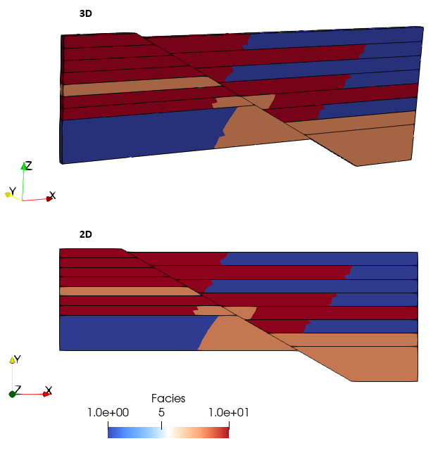
Results for the 2D and 3D cases
|

