Geometry Data
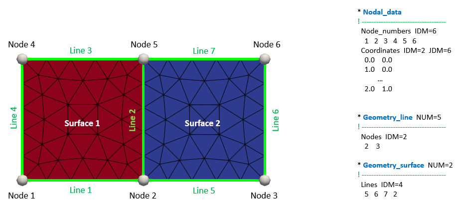
In ParaGeo the geometry of the problem domain is defined in terms of simple geometrical entities; i.e. points (vertices), lines, surfaces and volumes arranged in a hierarchical manner; i.e. points are used to define lines, lines are used to define surfaces and surfaces are used to define volumes (see figure below). All data assignments; loads, constraints, materials, etc are then assigned to these geometry entities rather than nodes and elements of the mesh (thus simplifying the input data). This also facilitates application of the assignments to new mesh discretisations that may be created by remeshing (regridding) operations.

Example of geometry entities defining the domain and mesh. Note that in this case Nodes correspond to the geometry vertex defined in Nodal_data.
Meshes may be generated internally in ParaGeo as the first (or prior) step of the simulation from a defined geometry in the datafile in ParaGeo format. The geometry entities to define the geometry comprise:
1Points (Geometry_vertex or Nodal_data).
2Lines (Geometry_line) - either linear, parametric or polylines defined using the points.
3Surfaces (Geometry_surface)- bounded by lines that form a closed loop and defined as either parametric or tesselated.
4Volumes (Geometry_volume) - closed volumes defined by surfaces.
Alternatively meshes may be pre-defined, either to be maintained throughout the simulation, or as a background grid to define the geometry; i.e. defining polylines and surface tessellations. Also meshes may be imported from external mesh generators (i.e. Abaqus hypermesh) and ParaGeo will generate the required geometry entities from the imported mesh.
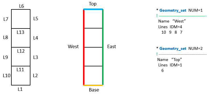
Geometry entities may also optionally be grouped into geometry sets using the data structure Geometry_set (see the picture below). This may be convenient to simplify assignments to several geometry entities at once e.g. a prescribed displacement value is applied to each individual line of a boundary in a 2D problem that is identified via a Geometry_set.

Example of geometry set usage.
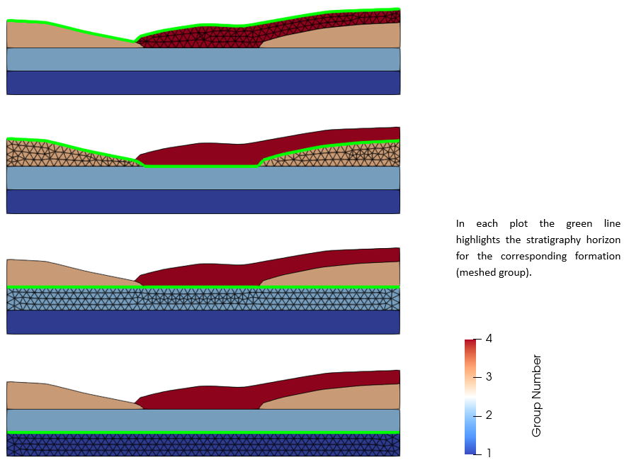
It should be noted that in ParaGeo, Groups (Group_data) are used to define a collection of surfaces (2D problems) or volumes (3D problems) with common material assignments. In geology-related problems a group is the equivalent of a formation or stratigraphy layer. Stratigraphy_definition is used to define the stratigraphic sequence (group sequence) in the initial model geometry. Note that identification of the Stratigraphy_horizon for each group is required (lines in 2D or surfaces in 3D defining the top of the stratigraphic units). Note that neither groups nor stratigraphy are data structures considered in the category of geometry definition.

Example of a geometry with 4 ParaGeo groups (formations) defined with 5 surfaces. The green line indicates the stratigraphy horizon corresponding to each formation (meshed group).
Notes
1Subsequent to initial mesh generation the geometry entities are defined by the topology of the finite element mesh; i.e.
(a) All lines become polylines.
(b) All surfaces become tessellated surfaces.
2For certain classes of analysis geometry may be either added, modified or removed by geometry update operations. These include:
(a) Sedimentation processes: Where additional stratigraphy units are added during the simulation, either as a single surface or volume for layer-cake deposition, or as multiple surfaces and volumes where the existing geometry intersects the sedimentation horizon.
(b) Stratigraphy pinchout, resulting in the sub-division of a stratigraphy layer into discrete regions defined by smaller surfaces or volumes.
(c) Eulerian boundary surface movement, resulting in the addition or removal of sediment to an existing stratigraphy unit, surface or volume.
3Optionally a mesh generation step may be performed without performing a simulation. This allows optimisation of the mesh prior to undertaking the simulation (see Mesh_control_data). Then the optimised mesh and the geometry can be stored in a .geo file (hdh5 format) that can later be read for the simulation (see The .geo file).
Examples
Most tutorial examples demonstrate definition of geometry data in ParaGeo.
For examples demonstrating usage of geometry sets:
Intro_001: Case02 Usage of Geometry Sets
