Case02 Mesh Regions to define element size
In the present case the logic behind mesh regions will be demonstrated. Mesh_region data structure may be used to define regions in the space with a target element size. Then all geometry points of the domain located within such mesh region will be assigned such element size. Two cases with identical mesh generation data including:
1. Default element size of 80 m
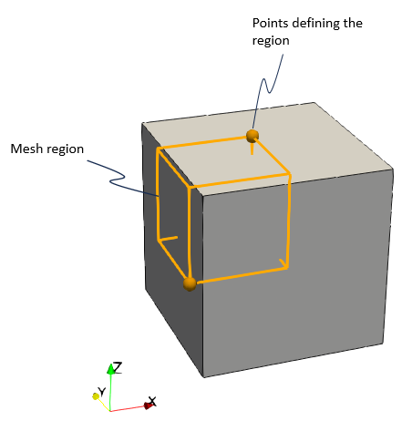
2.A "rectangular" Mesh_region (a rectangular prism in 3D) located in one of the corners of the cube geometry with a target element size of 20 m
Will be used to demonstrate Mesh_region usage and limitations (note that the refereed method for defining mesh with regions of different element sizes is via adaptivity) . The two cases provided in Mesh_002\Case02\Data differ in the geometry definition data as follows:
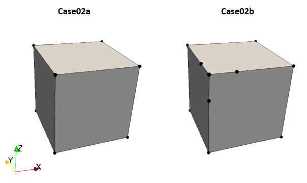
•Mesh_002_Case02a.dat : Same cube as in previous cases, defined by 8 nodes, 12 lines, 6 surfaces and 1 volume
•Mesh_002_Case02b.dat : Similar cube where 3 extra nodes and 3 extra lines have been defined which are located within the defined mesh region in the corner of the cube (see figure below).

Geometry for the two cases with the nodes defining the geometry
Below a description of the data files is provided. It should be noted that only the data relative to mesh generation will be described in detail while for the remaining data a brief description is provided.
Datafile Description
The basic data includes:
1.Geometry definition data (Nodal_data , Geometry_line , Geometry_surface and Geometry_volume ) at the end of the file after the END DATA command to define the cube geometry. 2.Group_data and Group_control_data for a single group with TET4V elements (note that the Element_type defined must be valid for the type of mesh being generated) 3.Material_data and Fluid_properties defining an elastic material 4.Support_data defining displacement fixities in the 3 directions for the whole cube volume (by assigning the corresponding Displacement_codes set to the internal Geometry_set "All_volumes" ) 5.Mesh generation data (Mesh_control_data, Unstructured_mesh_data and Mesh_region) with identical data for both cases. 6.Control_data defining the Duration of the simulation stage, the Target_number_time_steps for the stage as well as several output options.
Mesh Data
|
| Results |
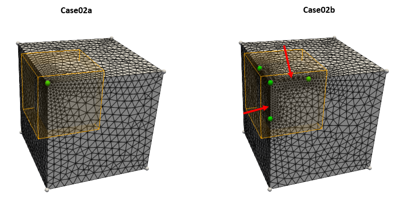
The results for the two cases are provided in: Mesh_002\Case02\Results. In the figure below it can be seen that in case02a the mesh region only has an effect in prescribing an element size of 20 m in the geometry point at (x, y, z) = (0, 0, 1000). In case02b the three extra points / nodes used to define the geometry are also located within the mesh region and therefore will have a prescribed element size of 20 m. Consequently the lines joining the points within the mesh region have a consistent element size of 20 m as indicated by the red arrows.
As may be anticipated, defining a mesh with different target element sizes at different parts of the domain may be cumbersome via Mesh_region. Thus a more flexible and easy way to achieve that is by remeshing the initial meshed geometry via adaptivity as demonstrated in Case03.
Results for the two cases with the mesh region in orange and the geometry points affected by the mesh region in green. The unaffected points are shown in grey
|


