Val_004a Internally Pressurized Cylinder
Problem Description
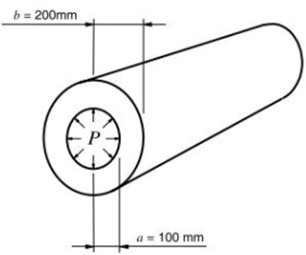
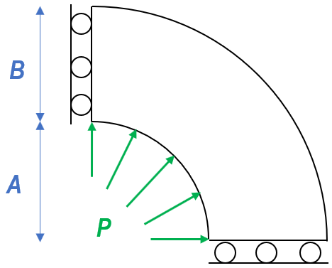
A long metallic thick-walled cylinder is subjected to internal pressure P, which is increased gradually until a collapse pressure Plim is reached. This is a state at which the plastic front, originated from the inner radius, has reached the outer radius. The collapse pressure is predicted using von-Mises model. A plot of internal pressure versus radial displacement on outer surface is to be plotted. The vertical and horizontal boundaries are constrained with symmetry boundary conditions.
The theoretical limit load for this problem was derived by Hill, expressed by
|
Mesh Discretisation
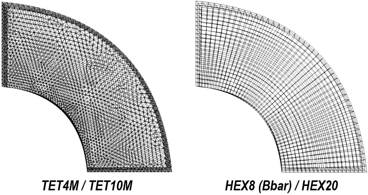
Twenty-four element types have been used in this test case, with 17 element types for implicit analysis and 7 types for explicit analysis. The followings illustrate some examples of meshed models that have been used in 2D and 3D cases.
Example of meshed models for 2D cases
Example of meshed models for 3D cases
|
Data File Descriptions
The data files for the different element types are in Val_004\cylinder. The different cases are in different sub-folders according to the dimensions (2D/3D), solver (explicit/implicit) and element type used for each specific case.
The basic data includes: 1Geometry_data imports geometry file for 3D cases in *.geo format that has been created using Gmsh and made compatible using ParaGeo pre-processing procedures. In 2D cases, the geometry is created directly through data file without the aforementioned pre-processing. 2Geometry_set groups multiple geometry entities under convenient geometry set names. 3Group_control_data activates geomechanical field for the current simulation group. 4Group_data sets the group name, element type, material name, porous flow type and the associated volume entity. 5Material_data defines the material properties of the model. 6Support_data constrains the displacement freedom on each surface accordingly. 7Global_loads defines the prescribed surface normal load on the geometry set associated with the cylinder internal surface. 8Damping_global_data sets a global damping ratio of 2%. 9Control_data defines the solution algorithm (e.g. 1 for explicit transient dynamic algorithm, 7 for nonlinear implicit algorithm), termination time, etc.
Only key data structures are shown below.
Group_data
Material_data
Global_loads
|
Results
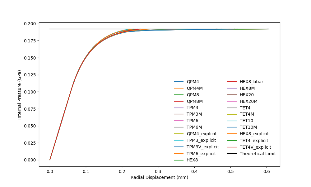
Overall, the simulation results converge to the theoretical limit load. The plots overlap each other in the elastic stage and also in the early stage of plasticity. As the plots draw closer to the limit load (0.19209GPa), we observe that the tangent modulus of 2D elements is slightly higher than the 3D counterparts, but they altogether approaches the limit asymptotically.
Load-displacement curve for internally pressurised cylinder. Comparison of numerical solutions derived from different elements with theoretical limit for both 2D and 3D cases.
The following figures show the standard results of internally pressurised cylinder. Plastic strain and stress variables are plotted at the final time step, corresponding to the near-collapse state as the limit load is approached. As the internal pressure increases, strain localisation gradually develops from the internal surface of the cylinder. We observe that plastic strain localisation is more distinct in 2D quadrilateral-based elements as well as 3D higher-order elements, suggesting that this group of elements is closer to the collapse state at the current time step than the elements that exhibit slightly more diffused strain localisation. Radial stress contour on the cylinder sample is also plotted for both 2D and 3D cases.
Plastic strain contour on selected element types
Radial stress contour on selected element types
|
References
[1] Hill, R. (1989). The Mathematical Theory of Plasticity (pp. 106, 254). New York: Oxford University Press. [2] Neto., E., Peric, D., & Owen, D. (2013). Computational Methods for Plasticity. Hoboken, N.J.: Wiley.
|


