Fract_002 Discrete Fracture Modelling

Contents
Introduction
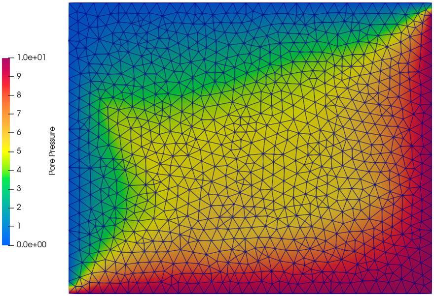
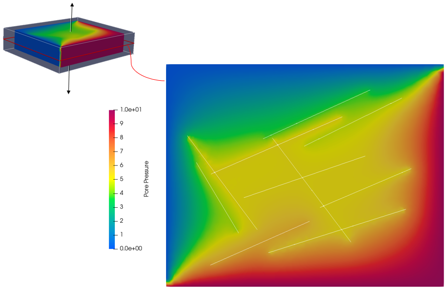
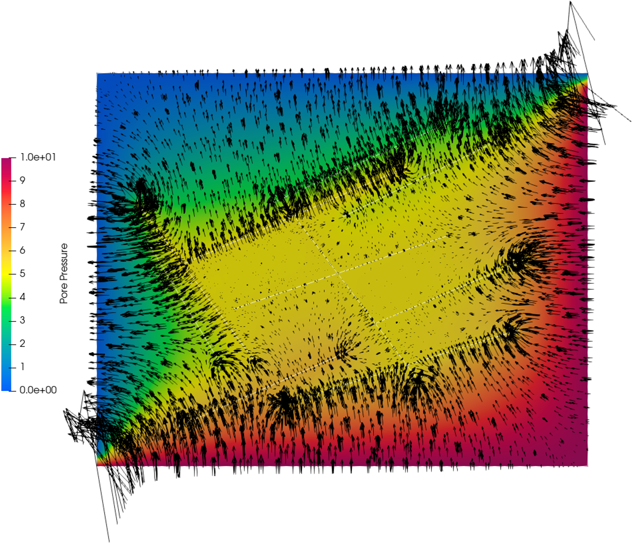
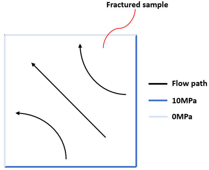
The aim of this example is to demonstrate procedures for importing the modified fracture data file from Fract_001 Case02 and running a simple steady-state flow (solved in a single time step) across the fractured medium. The simulation domain is the same as the example in Fract_001. In this example, we define a set of boundary and loading conditions for the fractured sample as follows: •Pore pressure of 10 MPa is prescribed on the east and south boundaries and pore pressure of 0 MPa is prescribed on the west and north boundaries. •The history of fluid volume and flow rate on the latter two boundaries are recorded. •All boundary surfaces are fully fixed. •The mesh size is set to be 10m.
Material Properties The properties used in this simulation test are listed below.
The additional material parameters related to the porous flow field are:
The additional material parameters related to the contact surfaces are:
|
The data files for this example (to be run consecutively) is in the directory: Fract_002\Data. It is defined in two parts, namely, data generation and simulation, in order that the simulation part can be run in parallel. The data generation part can only be run sequentially.
•Part 1: Generates a data file (.dat) and corresponding geo file (.geo) for use to run a simulation. Part 1 can only be run sequentially. fract_002_gen.dat (include file frac_sample_2.fab) -> fract_002_gen_exp.dat, fract_002_gen_exp.geo
•Part 2: Perform the simulation with the generated data (fract_002_gen_exp.dat) and geometry file (fract_002_gen_exp.geo) from Part 1. Part 2 can be run sequentially or in parallel.
Part 1 data includes the import of modified fracture data frac_sample_2.fab from Fract_001 Case02 and other data required for running a simulation (e.g. material, mesh, boundary condition, loading, history):
1Include imports FracMan-formatted modified fracture data frac_sample_2.fab from Fract_001 Case02. 2Contact_global defines the Contact_flow_flag=1 so that fluid may flow on the contact surfaces. 3Contact_property defines the mechanical and flow properties on the contact surfaces that are associated with the imported fracture data. 4Fracture_set assigns the fracture data to the contact property and volume geometry and the keyword Export_datafile_flag set to 1 will export a data file (.dat) and corresponding geo file (.geo) for use to run the simulation in Part 2. 5Global_loads prescribes pore pressure on the surfaces as described above. 6History_surface outputs the flow history data in terms of fluid volume and volume flow rate on the assigned geometry sets. 7Couple_control_data assigns respective fields that are coupled. In this case, they are geomechanical and porous flow fields. 8Porous_flow_control_data sets the solution algorithm for porous flow field.
Note that only key data structures are described below. |
Include imports FracMan-formatted fracture data.
|
Contact_global defines the Contact_flow_flag=1 so that fluid may flow on the contact surfaces.
|
Contact_property defines the mechanical and flow properties on the contact surfaces that are associated with the imported fracture data.
|
Fracture_set assigns the fracture data to the contact property and volume geometry as well as defining flags associated with the discrete fracture surfaces.
|
Global_loads prescribes pore pressure on the surfaces as described above.
|
History_surface outputs the flow history data in terms of fluid volume and volume flow rate on the assigned geometry sets.
|
Couple_control_data assigns respective fields that are coupled. In this case, they are geomechanical and porous flow fields.
|
Porous_flow_control_data defines the solution algorithm for porous flow field.
|
The result files for this example is available in directory: Fract_002\Results. The fluid volume and flow rate on the outlet surfaces are computed as follows. These values are used as benchmark for the homogenisation simulations in Fract_004 .
|