Problem description
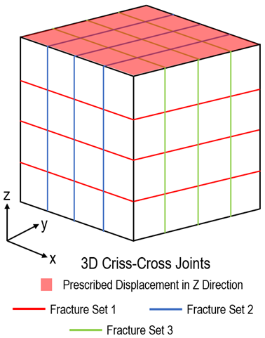
A 3D continuum model of size 1m x 1m x 1m is embedded with criss-cross joint sets, as illustrated in the figure below. The fracture spacing is 0.25m, and the fracture behaviour is governed by Bandis (nonlinear) model. There are three fracture sets in the model, such that each fracture plane is aligned to be normal to x, y and z axis respectively. The sample is subjected to uniaxial displacement of -0.1m in z-direction at top boundary under plane strain condition.

Continuum model embedded with criss-cross joint set
The goal of this inverse analysis is to recover fracture normal stiffness of all fracture sets as defined in Bandis model. The target solutions are Stress XX, Stress YY, and Stress ZZ.

Bandis model with initial stiffness (kn0 ) and initial aperture (d0 )
For the present case the target solutions are generated via a ParaGeo reference simulation with the data file defined according to the modelling descriptions above. The reference solution data file and results are provided in GeoInv_003\Reference_solution. The properties of the jointed rock, as defined in ParaGeo target data file, are tabled below. The arrangement of Fracture Set 2 and Fracture Set 3 are achieved by prescribing appropriate direction cosine values under Coordinate_system so that it remains normal to the loading direction.
Material Properties
The material properties corresponding to the jointed rock are given below.
Intact Rock Properties
|
Value
|
Young's modulus (MPa)
|
3000
|
Poisson's ratio
|
0.30
|
Porosity
|
0.20
|
Density (kg/m3)
|
2710
|
|
Fracture Properties
|
Fracture Set 1
|
Fracture Set 2
|
Fracture Set 3
|
Fracture spacing (m)
|
0.25
|
0.25
|
0.25
|
Initial normal stiffness (MPa/m)
|
1500
|
1000
|
1200
|
Initial aperture (m)
|
0.020
|
0.010
|
0.030
|
Maximum joint stiffness (MPa/m)
|
30000
|
30000
|
30000
|
|
Basic Set Up: Data file description
For the present case the inverted parameters (stiffness of the three fracture sets) are defined via arbitrary user-defined names. Consequently the template datafile is defined identical to the reference solution data file with exception that the parameters to be inverted are not input a value but rather are defined with "<p>ParameterName<p>" where "ParameterName" is the arbitrary name defined for such parameter. In the present case the three stiffness (one for each fracture set) that we aim to invert are named "Stiff1", "Stiff2" and "Stiff3" respectively. Below there is an example of the template data file.
Template File Setup
Keywords relevant to the setup of fracture with nonlinear stiffness are shown below.
Data File
|
|
* Fracture_data NUM=1
.
.
Normal_stiffness_model "Bandis"
Normal_stiffness_propertiesIDM=3
<p>Stiff1<p>
0.020
30000
* Fracture_data NUM=2
.
.
Normal_stiffness_model "Bandis"
Normal_stiffness_propertiesIDM=3
<p>Stiff2<p>
0.010
30000
* Fracture_data NUM=3
.
.
Normal_stiffness_model "Bandis"
Normal_stiffness_propertiesIDM=3
<p>Stiff3<p>
0.030
30000
|
1The normal fracture stiffness of the three fracture sets are named, respectively, "Stiff1", "Stiff2" and "Stiff3" under the Fracture_data data structure.
2It is important to include "<p>" before and after the ParameterName so that ParaGeoInv can identify the variables.
3These entries serve as placeholders for iterated values as the algorithm searches for optimal solutions.
|
|
In the following, we focus on the descriptions of ParaGeoInv data file provided in GeoInv_003\Data\GeoInv_003.inp. The basic data includes:
1Application_data identifies the directory of ParaGeo solver 2Parameter_data sets optimisation parameters, including variable name, initial value, minimum/maximum values, corresponding data structure name and number. In this example, the use of arbitrary defined parameter names is demonstrated. 3NA_options defines the tuning parameters of Nearest Neighbour algorithm and convergence tolerance. Users are also given flexibility to manage (i.e. keep or delete) the generated test models. 4File_data identifies the directory of template, target and test files. The name of template file is also required. 5Misfit_data_set specifies type of data to be compared between target and model solutions. The computation of corresponding misfit value is based on selected error type. 6Inverse_case chooses misfit data set(s) to be used. This data structure offers to run multiple cases, with the aim of homogenising the same optimisation variable.
Application_data
Application_data defines control data for inverse analysis, including application platform for forward analysis, experiment type and optimisation algorithm to be used.
Data File
|
|
* Application_data
Application "Parageo"
Inversion_algorithm "NAInverse"
Experiment "Material"
|
1ParaGeo is selected as the application platform.
2NAInverse (Nearest neighbour algorithm) is called. This is the only optimisation algorithm at the moment.
3Experiment type is set as 'Material'.
Note that the directory of ParaGeo identified via Executable_directory is not set. If not set (recommended) the executable in the PARAGEOHOME environment variable path will be used.
|
|
Parameter_data
Parameter_data defines parameter(s) and its range to be considered in inversion analysis.
Data File
|
|
* Parameter_data
Name IDM=3
"Stiff1" "Stiff2" "Stiff3"
Type IDM=3
0 0 0
Value IDM=3
1E2 1E2 1E2
Minimum_value IDM=3
1E2 1E2 1E2
Maximum_value IDM=3
1E4 1E4 1E4
|
1The optimisation variables, corresponding to the normal fracture stiffness of all fracture sets, are named "Stiff1", "Stiff2" and "Stiff3", respectively.
2Variable Type = 0 refers to parameter to be solved. In this case, all parameters are to be solved (value not prescribed).
3Values defined within the Value keyword are not used as all parameters are Type = 0.
4The minimum values of initial normal stiffness are 1E2 for all fracture sets.
5The maximum values of initial normal stiffness are 1E2 for all fracture sets. |
|
NA_options
NA_options defines the control options for the nearest neighbour algorithm.
Data File
|
|
* NA_options
Algorithm "Auto"
Convergence_tolerance 0.0005
Maximum_num_samples 40
Num_models_in_initial_sample 8
Num_models_in_sample 8
Num_models_in_resample 4
Number_models_output 5
Model_delete_option "KeepBest"
Model_clean_option "KeepSpec"
Model_results_keep IDM=1
"History"
|
1Algorithm = "Auto" refers to termination of computation once convergence tolerance is satisfied.
2Convergence_tolerance is set at 0.0005.
3Maximum_num_samples is set as 40.
4There are 8 models in the initial sample (Num_models_in_initial_sample).
5There are 8 models in subsequent samples (Num_models_in_sample).
6The 8 models in each subsequent sample (resample) are generated from the 4 best models.
7The 5 most optimal models will be output (Number_models_output) to the result file and will be the only ones for which the datafile in Test subfolder will be kept (Model_delete_option set to "KeepBest"). The model results kept for the best 5 models are the history results. |
|
File_data
File_data defines the working directories of data files that are crucial to the inversion analysis.
Data File
|
|
* File_data
Template_file "Case_3_fracture.dat"
Template_directory ".\Template"
Target_directory ".\Target"
Test_directory ".\Test"
|
1Template_file identifies the name of the template data file stored in Template_directory.
2Directory of target solution are stored in Target_directory.
3During optimisation computation, the generated model data files are stored in Test_directory. |
|
Misfit_data_set
Misfit_data_set specifies type of data to be compared between target and model solutions. The computation of corresponding misfit value is based on selected error type.
Data File
|
|
* Misfit_data_set NUM=11
Error_type "NormAve"
Experiment_filename "GeoInv_003_ref_001.hdh"
Experiment_variable_IDs IDM=3
"Strs_xx"
"Strs_yy"
"Strs_zz"
Model_set_number 1
Model_variable_IDs IDM=3
"Strs_xx"
"Strs_yy"
"Strs_zz"
|
1Error_type based on normalised average is specified.
2Target solution stored as "GeoInv_003_ref_001.hdh" is defined under Experiment_filename.
3Experiment_variable_IDs (target solution variables names used for misfit calculation) "Strs_xx", "Strs_yy" and "Strs_zz" are specified.
4Model_set_number is set as 1. This sets the model History_point set NUM=1 as the data source for comparison with the target solution.
5Model_variable_IDs "Strs_xx", "Strs_yy" and "Strs_zz" are specified. |
|
Inverse_case
Inverse_case chooses misfit data set(s) to be used.
Data File
|
|
* Inverse_case NUM=1
File_data_num 1
Misfit_data_sets IDM=1
11
|
1Inversion analysis is performed using data files and folders specified in File_data NUM=1 (File_data_num = 1), and misfit data set specified in Misfit_data_set NUM=11. |
|
|
Results
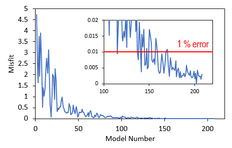
A number of 26 samples, comprising of 208 models have been performed before reaching convergence. Iteration was terminated when Model 202 was identified to satisfy the convergence criteria. It should be noted however that given the randomness of the inverted parameter values input for the generated models these results are only representative of the specific run used to generate the provided tutorial results. The result files for the project are in directory: GeoInv_003\Results.
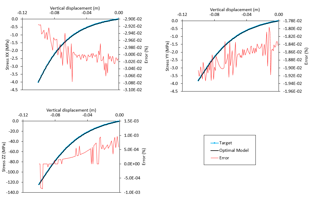
As shown in the plot below, a number of models with misfit value lower than 1% were identified towards the end of the inverse analysis. All stiffness values converge to a set of optimal solution (with stiffness for fracture sets 1 and 3 being inverted with 100% of accuracy), which reproduces the solutions of Stress XX, Stress YY and Stress ZZ comparable to target solutions. Low percentage error was observed.
Misfit Value

Reduction of misfit towards value lower than 1% error
Optimal Initial Normal Stiffness for the Three Fracture Sets

Nearest Neighbour algorithm in search of optimal initial fracture stiffness for the three fracture sets. Horizontal red lines indicate values used to generate target solution.
Comparison with Target Solution

Comparison of optimal model stresses with the reference solution stresses.
|


