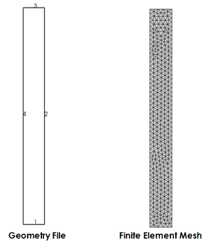
Case 1 Simple Rectangular Domain


Basic Set Up: Data File Description


The data file for the project is: mesh_001\Data\mesh_001_2d_Case1.dat. The description of the datafile is provided here in an order that facilitates understanding of the model definition incrementally (e.g. geometry first, then mesh, then groups, etc.) but the actual data may be placed in a different order within the datafile.


Geometry definition data

In ParaGeo the data concerning definition of the geometry is specified at the end of the data file, after the END DATA (which is a compulsory command indicating the end of the model general data and start of the model geometry data).


The geometry of the problem domain is defined in terms of simple geometrical entities; i.e. points (vertices), lines, surfaces and volumes arranged in a hierarchical manner; i.e. points are used to define lines, lines are used to define surfaces and surfaces are used to define volumes. The geometry entities comprise:


1Points (Geometry_vertex or Nodal_data).

2Lines (Geometry_line) - either linear, parametric or polylines defined using the points.

3Surfaces (Geometry_surface)- bounded by lines and defined as either parametric or tesselated.

4Volumes (Geometry_volume) - closed volumes defined by surfaces.


For the current problem a single rectangular surface is required which is defined by four linear lines.   Consequently four points must also be defined (see the figure below).
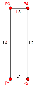
 

HM_clip0001

Points (nodes) and lines defining the model geometry


Nodal_data


The Nodal_data  data structure defines the coordinates of the points defining the geometry.


Data File


* Nodal_data  

 node_numbers IDM=4

    1  2  3  4

 coordinates IDM=3 JDM=4

 0.0   0.0  0.0

 1.0   0.0  0.0

 1.0  10.0  0.0

 0.0  10.0  0.0


1.In Node_numbers keyword the ID number of the four nodes defined is indicated

2.The four points coordinates are defined as shown in the following table:

Point

X-Coordinate

Y-Coordinate

Z-Coordinate

1

0.0

0.0

0.0

2

1.0

0.0

0.0

3

1.0

10.0

0.0

4

0.0

10.0

0.0


Geometry_line


The Geometry_line data defines the topology of the four lines consisting of the base, top and sides of the model surface.


Data File


* Geometry_line  NUM=1  

 line_type      1    

 points     IDM=2

   1  2  


* Geometry_line  NUM=2

 line_type      1    

 points     IDM=2

   2  3  


* Geometry_line  NUM=3

 line_type      1    

 points     IDM=2

   3  4  


* Geometry_line  NUM=4

 line_type      1    

 points     IDM=2

   4  1  


1.Each of the four lines defining model boundaries are assigned ID numbers 1, 2, 3 and 4.

2.Each line is connecting two points.

3.Line_type 1 keyword defines that the line is a linear line connecting two points.


Geometry_surface


Data File


* Geometry_surface NUM=1

 lines      IDM=4

   1  2  3  4  


1.The model domain is defined by a single rectangular surface which is assigned ID number 1 (NUM=1)

2.The surface is defined by the four lines with ID numbers 1, 2, 3 and 4.


Mesh definition data


Mesh_control_data


The Mesh_control_data data structure is compulsory and defines :

1The mesh generation algorithm type.  Valid values are:

1 - Structured mesh generation

2  - Unstructured mesh generation.

2Whether just mesh generation is to be performed.  An analysis step is performed by default if Mesh_generation_flag is not specified.


Data File


* Mesh_control_data

! ---------------------------------

 Generation_algorithm    2

 Mesh_generation_flag    1


An unstructured mesh generation algorithm is used and only mesh generation is performed (Mesh_generation_flag = 1).


Unstructured_mesh_data


The Unstructured_mesh_data data structure defines:

1The default target element size and upper and lower bound element sizes

2The quality target for tetrahedral mesh generation

3Target, minimum and maximum element sizes for specific lists of entities


* Unstructured_mesh_data

! ---------------------------------

 Default_element_size          0.2

 Element_size_bounds IDM=2

  /Max. Element Size/         0.2

  /Min. Element Size/         0.2


1.In the present case minimal data is defined specifying a target element size of 0.2 for the complete domain


Data for definition of Groups


ParaGeo groups are geometric regions with specific properties, material assignments, individual stratigraphy layers, etc. ParaGeo groups may encompass one or several surfaces in 2D problems and one or several volumes in 3D problems. Two compulsory data structures are used for the definition of ParaGeo groups; Group_data and Group_control_data


Group_data


The Group_data data structure is compulsory and defines the properties for each geometry group.  For this example these comprise:

1The name of the group.

2The element type.

3The surface that defines the geometry for the group.


* Group_data  NUM=1

! ---------------------------------

 Group_name                     "sand"

 Element_type                  "TPM3V"

 Surfaces  IDM=1

     1


Group 1 (NUM=1) is named "Sand" and is defined using the TPM3V (Triangle Plane Membrane with 3 nodes using the average Volume formulation).  The geometry of the group is defined by surface 1.


Group_control_data


The Group_control_data  data structure is compulsory and defines:

1The number of geometry groups in the problem, where each geometry group relates to a region with specific properties; e.g. regions with different material assignments, individual stratigraphy layers, etc.

2The group number.

3Whether the group is active or inactive in the fields; i.e. geomechanical, porous flow, thermal, that are being solved.


Data File


* Group_control_data

! ---------------------------------

 Group_numbers  IDM=1

     1  

 Active_geomechanical_groups  IDM=1

     1  


The problem has a single group (Group 1) that is active in the geomechanical field.


Control_data

At least one solution control data structure must always be specified. This data structure defines the end of each simulation stage. For each stage this data structure defines the solution algorithm, termination time, step control and output frequency data for screen, plot file and restart fields.  The specific keyword used is dependent on the analysis type or active fields with valid types being:

1Control_data - control data for the geomechanical field.

2Porous_flow_control_data - control data for the porous flow field.

3Thermal_control_data - control data for the thermal field.


In a coupled simulation more than one keyword may be specified (e.g. Control_data and Porous_flow_control_data) in conjunction with Couple_control_data, which defines the active fields. Nonetheless in most coupled simulations only Control_data and Couple_control_data are required and the data relevant for the fluid flow/thermal fields is defined within Control_data.


Once a control data keyword is processed, ParaGeo processes this control step before reading any further data from the data file.


Data File


* Control_data

! ===================================

 Termination_time              1.0


Control data for the geomechanical field is specified with the minimum allowable data being the termination time.  Note that, although compulsory, in this case this data is not used as only a mesh generation is performed.


END DATA

The END DATA command signifies the end of the analysis data file and the start of the geometry definition.


Data File


END DATA

The END DATA command is compulsory


Results

The result files for the project are:

mesh generation results

mesh_001\Results\mesh_001_2d_Case1_mesh.xmf

Geometry results

mesh_001\Results\mesh_001_2d_Case1_gmr.xmf


The expected finite element mesh is shown below

HM_mesh_001_02