01 - Geometry Definition
The present example considers generation of the 2D present day geometry defined in a CAD type file with extension .dxf. In this section the proper preparation of the .dxf as well as the conversion data files are discussed. The data files are provided in Geol_001 \01_Geometry_Generation\Data which include
•Geol_001.dxf : File containing the CAD geometry that will be converted to .geo geometry.
•Geol_001_Reference.dwg : File containing the CAD geometry for the full Orange Basin section (not used in this example, only provided for reference).
•Geol_001_geom_Step1.dat : Data file with data to read the .dxf and convert to .geo.
•Geol_001_geom_Step2.dat : Data file to read the converted .geo and output a meshed geometry plot file to facilitate data checking and fault hanging wall and footwall identification.
•Geol_001_geom_Step3.dat : Check data and identify fault hanging walls and footwalls.
In order to keep the model reasonably simple for demonstrative purposes, only the two compressional faults further to the left will be considered. Also a thin sediment wedge at the top left corner has been considered to be the same group as the layer below. The base of the model geometry will be defined thick and will be assigned relatively stiff properties in order to prevent excessive bending of the detachment due to the flattening of the fault-related anticlines during restoration.
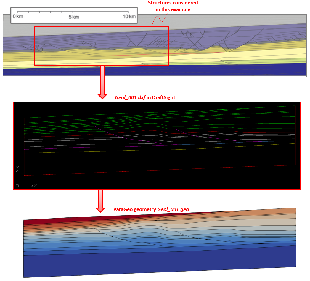
Image of interest -> Geometry .dxf definition in DraftSight -> Conversion to ParaGeo geometry .geo
The flowchart below summarises the files involved in the geometry generation process from the prepared .dxf file to a meshed .geo file as described in this section of the manual.
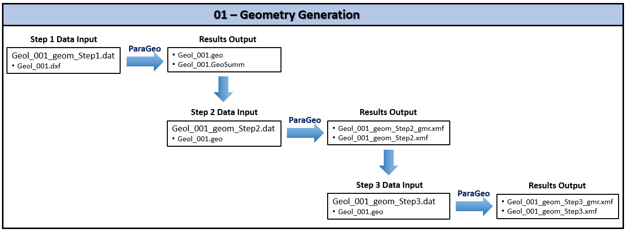
Summary flowchart of files involved in geometry generation process from prepared .dxf file to meshed .geo file.
Geometry .dxf preparation
Before defining the .dxf geometry, the following steps are undertaken to obtain a background reference image to superimpose and draw the geometry on top:
1.Copy paste / Import a picture / screenshot of the section of interest into the CAD software (e.g. DrafSight, AutoCAD). 2.Make sure the image has the correct size. Reference lines can be drawn on top of the image visual scale to work out the required scaling factor to be applied to the image.
Then the definition of the geometry lines is done on top of the background reference image. Following are notes on how to properly define the geometry lines so that the resulting .dxf geometry is suitable for conversion:
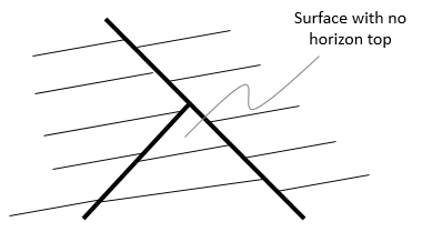
1.Only line and polyline entities are supported (polylines are generally recommended). 2.All lines and polylines should be split / terminate at every intersection with another line (see picture below). This will ensure that enclosed surfaces can be generated. 3.All lines must have both edge points connected to at least another line / polyline (i.e. fault tips interior to a surface are not allowed for example, see picture below). 4.Faults are represented by a single line that will be split into a hanging wall and footwall parts during .dxf to .geo conversion.
Splitting of lines / polylines in CAD software
Termination of lines / polylines in CAD software
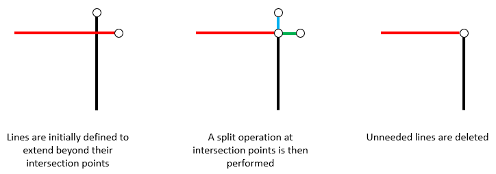
It should be noted that most common errors in conversion are because lines that visually appear to be connected, in reality they are not. This may be due to the functionality to track / connect points based on proximity in the CAD software being not active when drawing that line for example. Thus it is generally recommended to first define the lines to extend beyond other crossing lines, then perform a line split at the intersection point and finally delete the unneeded lines (see picture below).
Workflow to split line / polyline in CAD software
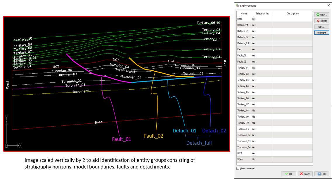
When the geometry lines and polylines are properly defined, the next step is to group them using the entity grouping functionality of the CAD software. Every entity group will be converted to a ParaGeo geometry set during .dxf to .geo conversion so the entity groups should include boundaries, stratigraphy horizons, faults, etc. Additionally ParaGeo includes functionality to use entity groups corresponding to stratigraphy horizons to automatically generate ParaGeo groups with the corresponding surfaces. Also splitting of fault lines into the corresponding fault hanging wall and foot wall will be performed by providing the corresponding entity group name during .dxf to .geo conversion.
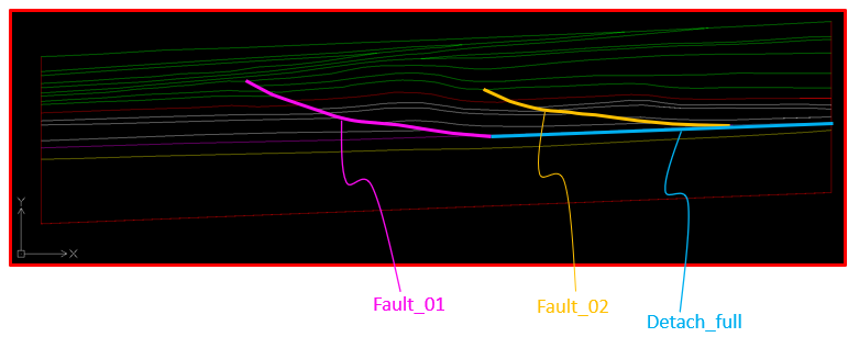
The present case includes entity groups for every stratigraphy horizon, every model boundary, every fault, every separate detachment line and one encompassing the two detachment lines to facilitate split. Note that all stratigraphy horizons span from the west boundary to the east boundary with some split by the two faults and some sharing the same lines due to layer pinchout, e.g. Tertiary_04 and Tertiary_05 share the same line on the west boundary and Tertiary_06 to Tertiary_10 share the same line on the east boundary.
Definition of entity groups in DraftSight (include stratigraphy horizons, model boundaries, faults and detachments)
The geometry must be saved as a .dxf format (ASCII R2013) for ParaGeo conversion.
|
Step 1: .dxf to .geo conversion
•The .dxf to .geo conversion datafile includes data to read the .dxf file, split the contact surfaces (detachments and faults) and automatically generate stratigraphy data and groups from the specified entity groups stratigraphy horizons. •The outcome of this Step 1 simulation are the files Geol_001.geo and Geol_001.GeoSumm which are required for Step 2.
Read the .dxf geometry
Separate contact surfaces
Generation of groups and stratigraphy data
Output of the .geo file and a geometry plot file
|
Step 2: Output of a meshed geometry plot file
The purpose of this steps is to output a meshed geometry plot file that can be easily visualized in ParaView. To that end only a single mechanical step will be run with all the geometry fully fixed to prevent any movement: •Step 2 data file comprises the geometry data extracted from the Step 1 Geol_001.GeoSumm file, namely the Geometry_data, Group_data, Group_control_data, Geometry_set, Stratigraphy_definition and Stratigraphy_horizon data structures. Accordingly it needs to read in these data from the Step 1 geometry file Geol_001.geo. •Additional data is also required to facilitate generating a mesh and performing a single analysis step in order to output a meshed geometry plot file. These include data structures Material_data, Fluid_properties, Support_data, Mesh_control_data, Unstructured_mesh_data, Damping_global_data and Control_data.
Geometry_data, Group_data, Group_control_data, Geometry_set data The following data structures are copy / pasted from the Geol_001.GeoSumm file.
Defining the Stratigraphy The following data is copy / pasted from the Geol_001.GeoSumm file with additional edits to remove unnecessary data.
The stratigraphy is defined by: 1Defining the existing stratigraphy layer depositional order and the group associated with each layer (via Stratigraphy_definition) from oldest to youngest. 2Defining the topology of the top surface horizon for each stratigraphy layer including basal horizon (via Stratigraphy_horizon). The stratigraphy is defined in a similar way to Mech_002 where there is a fuller description provided. Note that in geomechanical restoration simulations the definition of the stratigraphy is compulsory.
Material Data The material properties for the material "Elastic" as well as its associated fluid properties are defined in the datafile. Note that the property values defined here are not important as the model will be fully fixed and a single analysis step performed.
Support Data The support data is used to define the fixity for all surfaces to be fully fixed in the X and Y directions.
Mesh Data An "unstructured mesh" with minimum element size of 50m and default / maximum element size of 80m and 125m size is defined for this example.
Control Data A single control stage defined by the Control_data data structure is utilised to perform a single mechanical step for the sole purpose of outputting a meshed geometry plot file in this Step 2 workflow.
|
Step 3: Data correction and fault side identification
The purpose of Step 3 within the geometry preparation workflow is to visualise the geometry meshed during Step 2, check and correct the data when necessary and identify fault hanging walls and footwalls. Note that:
•For this example, the ParaGeo group data and stratigraphy data generated in the Step 1 workflow is correct, so no corrections are required in this Step 3 workflow. Consequently, the Step 3 data file is exactly the same as the Step 2 data file with the exception of the geometry set name changes to identify the fault hanging wall and footwall parts for Fault_01, Fault_02 and Detach_full.
•These geometry sets were split in the Step 1 workflow and the names of the split surfaces were automatically appended with _1 and _2 in the Geometry_set data. These six geometry sets will now be renamed with the handing wall and footwall identifiers.
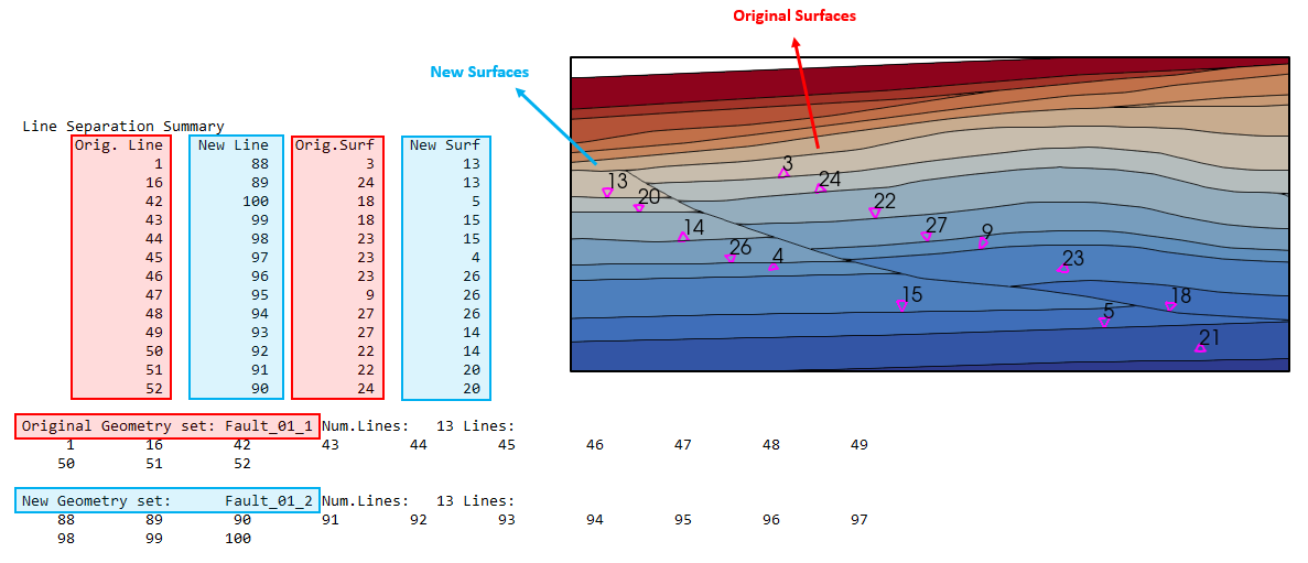
•To identify which separation lines are hanging wall and which are footwall, refer to the line separation summary in the Geol_001_geom_Step1.res file. In such file "Orig. Line" column indicates the original line numbers in the geometry set while "New Line" column indicates the numbers of the new lines generated after the split. Lines in "Orig. Line" column are contained in surfaces listed under "Orig. Surf" column. Likewise lines listed under "New Line" column are contained in surfaces under "New Surf" column. Using this information and the visualisation of the surface numbers in Geol_001_geom_Step2_gmr.xmf in ParaView, we can work out which lines belong to the hanging wall and which belong to the footwall. The picture below shows that in this example Line 1 (contained within Fault_01_1) is contained in surface 3 which is on the hanging wall. Hence, after checking all the lines and surfaces it can be identified that "Fault_01_1" is the hanging wall and "Fault_01_2" is the footwall.
Identification of "Fault_01" hanging wall and footwall parts through "Line Separation Summary" in Geol_001_geom_Step1.res file and visualisation of surface numbers in Geol_001_geom_Step2_gmr.xmf in ParaView
|
Results
The result of this procedure is the .geo file from Step 1 and data structures defined in the Step 3 data file that will be used to define the restoration data.
ParaGeo .dxf to .geo model plot file
|


