Rest_003_Rest Restoration model


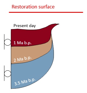
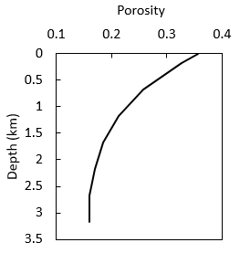
For the restoration model the initial geometry considers only the sediments to be restored (salt is removed). In the figure below the geometry and boundary conditions is shown. The sediment horizon ages is indicated. The porosity trend to initialize the simulation and to perform the decompaction is shown below.


Look for ! TODO  text in the datafile and follow the instructions.
 

Rest_003_02             Rest_003_03

Restoration model geometry and boundary conditions (left). Porosity trend to initialize the model and perform vertical decompaction (right).


Basic Set Up: Data File Description


The initial data file for the project is: Rest_003\01 Restoration\Data\Rest_003_Rest.dat.   Look for ! TODO  text in the datafile and follow the instructions.  The basic data includes:
 

1Geometry_data to read the .geo file containing the geometry

2Group data for the three formations which are assigned the "Elastic_dec" properties using Group_control_data and Group_data data structures.

3Geometry_set data defining two model boundaries

4Stratigraphy_definition and Stratigraphy_horizon identifying the three formations top horizons.

5A Material_data and Fluid_properties data structures defining elastic material properties with vertical decompaction.

6Geostatic_data, Spatial_variation_definition and Spatial_variation_values to define the initial porosity trend vs depth to initialise the model. Note that this Spatial_variation_definition is also assigned in Material_data in order to perform the vertical decompaction.

7A second set of Geostatic_data, Spatial_variation_definition and Spatial_variation_values that will be included in the exported isopachs to perform pre-compacted sedimentation during the forward simulation.

8Support data (Support_data) defining fixity in X direction at the pin line location (West_fix).

9Mesh control (Mesh_control) and Unstructured mesh generation data (Unstructured_mesh_data) defining an element size between 50 m and 100 m.

10Restoration_data defining:

(a) Assignment of restoration surface

(b) The restoration operation (i.e. Translate for first stage and Restore for subsequent stages)

(c) Decompaction type (set to None for first stage and continuous for subsequent stages)

(d) The time curve for the decompaction

(e) Data related to the isopach output

11Part geometry data (Part_geometry_set, Part_line and Part_nodal_data) to define the restoration surface

12Time scaling data (Time_scaling_data) with optimal time step 1E-5 Ma.

13Damping data (Damping_global_data) to define bulk damping on the effective mean stress (Bulk Viscosity model)

14Control data (Control_data) for three stages defining:

(a)  Incremental solution algorithm (Type 1),

(b)  Maximum number of time steps of 108 (very large to avoid premature termination)

(c)  Durations of 1 Ma, 1 Ma and 1.5 Ma for the three stages.

(d)  Factor of critical time step = 0.5,

(e)  Plot file output every 0.2 Ma,

(f)  Plot file output at the end of the stage,

(g)  Screen message output every 1000 mech steps,

(h) Output of a restart file at the end of the stage.


The aim of the present tutorial example is to demonstrate the restoration to forward simulation work flow for mini-basins type models. Thus the user is assumed to have undertaken other tutorial examples previously and be familiar with most basic data structures so only the most relevant data structures or data set up for the present case will be described in detail.


Geometry_data


Data File


* Geometry_data

! ----------------------------------------

 File_name      "Rest_003_Rest.geo"

 File_format                    hdf


1The geometry for the problem is read from an external .geo file.


Material_data


Data File


* Material_data                    NUM=1  

! ---------------------------------

 Material_name            "Elastic_dec"

 Isotropic_elastic_properties     IDM=2

  /Young's Modulus/              10000

  /Poisson's Ratio/               0.20

 Grain_density                     2760

 Grain_stiffness                  30000

 Porosity                          0.50        

 Singlephase_fluid                    1  

 Decompaction_Type                    1  

 Decompaction_spatial                 1


* Fluid_properties NUM=1

! ---------------------------------

 Fluid_type                      "Water"

 Density


1The present case considers vertical decompaction (Decompaction_type 1).

2Decompaction_spatial set to 1 assigns the Spatial_variation_definition NUM=1 (which in turn is assigned porosity vs. depth trend in Spatial_variation_values NUM=1) to perform decompaction operations.


Restoration_data


The present example demonstrates automatic output of restored isopachs for usage during forward modelling. This data output is specified within Restoration_data data structure via specification of Isopach_output 1 keyword. Each isopach is output as a Sedimentation_horizon data structure together with the corresponding Sedimentation_data and Control_data into a data file named Rest_003_Rest_GroupName.dat where GroupName is the name of the formation being back-stripped. Note that material, geostatic set and number of flow steps for the generated data may also be specified.


Note that the generated data for the duration of each sedimentation stage during forward modelling will be consistent with the corresponding restoration stage.


Data File


* Restoration_data

! ---------------------------------

 Restoration_surface       "Restoration_surface"

 Operation_type            "Translate"

 Decompaction_Type         "None"

 Isopach_output            1

 Isopach_geostatic_set     "Sedimentation"  

 Isopach_material_name     "Shale"

 Isopach_material_file     "2D_Minibasin.mat"

 Isopach_flow_steps        400


* Part_geometry_set         NUM=1

! ---------------------------------

 Name    "Restoration_surface"

 Part_lines      IDM=1

   1


* Part_line                  NUM=1

! ---------------------------------

 Facets      IDM=2  JDM=1

   1  2


* Part_nodal_data           NUM=1

! ---------------------------------

 Nodes      IDM=2

   1 2

 Coordinates   IDM=2 JDM=2

   -10.0  6000.0

  5000.0  6000.0


1A Restoration_data structure is defined (compulsory for geomechanical restoration simulations).

2The part geometry named "Restoration_surface" is assigned as a restoration surface.

3The restoration operation for the first control stage is set to "Translate" (the model top surface is "back-stripped" to the restoration surface). For next stages the Operation_type is set to "Restore" (remove current top formation and back-strip new top surface).

4Decompaction_type is set to "None" for the first stage as the initial porosity distribution prescribed for model initialization is the same as the porosity trend used for decompaction. For subsequent stages it is set to "Continuous" (continuous decompaction over the duration of the simulation stage).

5Isopach_output set to 1 indicates that at the end of each restoration stage the isopach for the back-stripped sediment will be output to a .dat file together with the corresponding Sedimentation_data and Control_data for usage during forward modelling.

6Isopach_geostatic_set assigns Geostatic_data named "Sedimentation" for the sedimentation of the output isopach (this will be included in the generated Sedimentation_data). In such a way during forward simulation the sediment will be deposited at a pre-compacted state following the porosity-depth trend specified in the assigned geostatic set.

7Isopach_material_name "Shale" and Isopach_material_file "2D_Minibasin.mat" define the material for the deposited isopach during forward modelling (this will be included in the generated Sedimentation_data).

8Isopach_flow_steps set to 400 defines the number of flow steps used for the deposition of the isopach during forward modelling (this will be included in the generated Control_data).

9Part geometry data (Part_geometry_set, Part_line and Part_nodal_data) is used to define the restoration surface consisting of an horizontal line with Y=6000 m.


Results


The result files for the project are in directory: Rest_003\01 Restoration\Results.


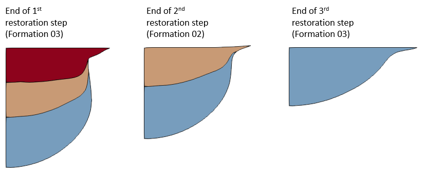
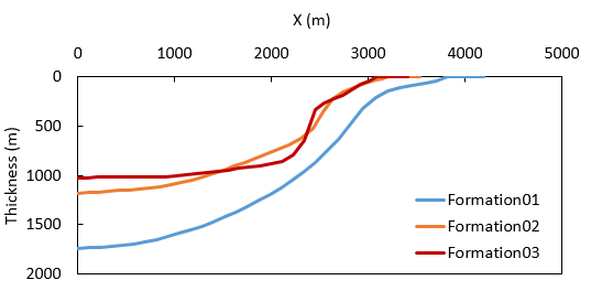
In the figures below it can be seen the geometry configuration at the end of each restoration step and the matching output isopachs.  In the output .dat files containing data for sedimentation of the isopachs and corresponding control data it can be seen that


1.A Sedimentation_horizon data structure is generated for each isopach.

2.The generated Sedimentation_data contains information about the material, material file and geostatic set assigned for the isopach to be deposited

3.The duration of each stage is consistent with the restoration step of the corresponding formation.

4.The Initial_time_increment is defined according to the duration of the stage and the defined Isopach_flow_steps


Rest_003_04

Geometry configuration at the end of each restoration step


Rest_003_05

Output isopachs