Case01 and Case02 Comparison of node-to-node and node-to-facet contact algorithms


Basic Set Up: Data File Description

The initial data file for the project is: Cont_003\Data\Cont_003_Case01.dat.   The basic data includes:


1Geometry_data to read the .geo file containing the geometry and mesh.

2Geometry_set data for all model boundaries, fault and detachment surfaces and stratigraphic horizons.

3Contact data (Contact_set, Contact_property, Contact_surface and Contact_global).

4Group data for the four formations  (Group_control_data and Group_data).

5Material_data and Fluid_properties defining the elastoplastic properties for all formations.

6Support_data to define displacement constrains to the boundaries.

7Gravity_data for gravity initialisation during the first stage.

8Geostatic_data assigning the initial porosity distribution and Geostatic_control_data appropriate for each initialisation stage defined within the geostatic.set file.

9Load data and the associated time curve defining a tectonic compressive displacement of 80 m applied during the second stage to the East_top boundary (Global_loads, Time_curve_data and Load_case_control_data).

10Damping_global_data defining a velocity damping (Percentage_damping) of 0.02

11Control data (Control_data) for four stages defining:

(a)  Factor of critical time step = 0.5,

(b) Incremental solution algorithm (Type 1),

(c)  Maximum number of time steps of 106 (very large)

(d) Target_number_time_steps of 10000 per stage

(e)  Stage duration of 0.25 Ma each,

(f)  Plot file output at the end of each stage,

(g) Plot file output every 0.05 Ma,

(h) Screen message output every 500 mech steps.


Contact Data


Here the contact data for the present example is discussed. Note that data for cases Case01 and Case02 is almost identical except that in Case01 the node-to-node algorithm is adopted as opposed to Case02 in which node-to-facet algorithm is used. This is defined using the keyword algorithm within the Contact_global data structure. The contact data encompasses Contact_global, Contact_set, Contact_property and Contact_surface data structures.


Contact Global data


Data File


* Contact_global

! ----------------------------------

 Included_contact_sets  IDM=1

   "All"

 Algorithm    2


1.There is only one contact set in the present case which is named "All".


2.The Algorithm is set to 2 (node to node algorithm) for Case01 whereas for Case02 is set to Algorithm 1 (node to facet contact - default).


3.It should be noted that Algorithm 2:


a.Is better suited for small displacement problems (less than half of the element length)


b.Is better suited for consistent (matching) meshes between contacting surfaces


c.Only allow 1 to 1 contact so that each surface should only be able to establish contact with another surface (no more than one). If for any contact surface interaction with more than one other contact surface is allowed, the simulation may run but the results will not be meaningful.


d.It is recommended to use Slip_update_model 2 in Contact_set data, which is designed for static/present day models.


Contact Set data


In this case a single Contact_set data is defined which encompasses all the contact surfaces. It is noted that for node-to-node algorithm contact interactions should be limited so that each contact surface can only interact with another contact surface (no more than one). This may be achieved by defining different Contact_set data for each pair of contact surfaces or by defining Contact_surface data structures which establishes the allowed interactions. In the present case the later method is used.


Data File


* Contact_set                  NUM=1

! ----------------------------------------

 Name      "All"

 Geometry_sets IDM=4

  "Fault_ftw"

  "Fault_hgw"  

  "Detachment_hgw"

  "Detachment_ftw"

 Algorithm                   "Penalty"

 Property_name               "Block_friction"

 Global_update_frequency     200

 Field_factor                0.2

 Buffer_factor               0.5

 Trigger_search_velocity     10

 Slip_update_model           2


1The Contact_set is named "All"


2The four contact surfaces Fault_hgw, Fault_ftw, Detachment_hgw and Detachment_ftw are included in the Contact_set.


3The penalty algorithm is used for the contact set (only option currently available).


4The Contact_property named "Block_friction" is assigned by default to all the contact surfaces included in the contact set.


5A global contact search to update the contact lists is performed every 200 mechanical time steps.


6The field factor is set to 0.2 (two nodes are in contact if the penetration distance between them is 0.2 · lfacet or less, where lfacet is the facet length).


7The buffer factor for defining the buffer box size is set to 0.5 (the candidate target nodes that can potentially establish a contact relationship with a given contactor node are those within the buffer box during a global search update). In this case the buffer box for a given node is an sphere centred at the node with radius R=0.5 lfacet  where lfacet is the average length of the facets connected to the node.


8If a point (node) exceeds the Trigger_search_velocity of 10m/Ma (problem units) a global update search will be triggered. This option can help to prevent loss of contact and leaking meshes when the velocity of a node is relatively high.


9The Slip_update_model is set to 2, which is recommended for quasi-static small displacement problems.


Contact Surface data


Data File


* Contact_surface  NUM=1

! ------------------------------------------

 Name                        "Fault_ftw"

 Surface_interaction  IDM=1

   "Fault_hgw"


* Contact_surface  NUM=2

! ------------------------------------------

 Name                        "Fault_hgw"

 Surface_interaction  IDM=1

   "Fault_ftw"        


* Contact_surface  NUM=3

! ------------------------------------------

 Name                        "Detachment_hgw"

 Surface_interaction  IDM=1

   "Detachment_ftw"


* Contact_surface  NUM=4

! ------------------------------------------

 Name                        "Detachment_ftw"

 Surface_interaction  IDM=1

   "Detachment_hgw"        


1.Four Contact_surface data structures are defined in order to establish the allowed interactions between contact pairs (e.g. Fault_ftw is only allowed to contact Fault_hgw and vice-versa).


Contact Property data


Data File


* Contact_property             NUM=1

! ----------------------------------------

 Name      "Block_friction"

 Compression_model                       1                  

 Compression_properties IDM=1

  /"Normal Penalty"/                  500

 Tangential_model                        2                  

 Tangential_properties IDM=2

  /"Tangential Penalty"/             500

  /"Friction coefficient"/            0.1

 Contact_damping_factor                0.1        


1.A single Contact_property is defined and assigned to all contact surfaces. The property data defines:


a.Elastic penalty based compression model (Compression_model 1) with a contact normal stiffness of 500 MPa


b.Coulomb Tangential model (Tangential_model 2) with a tangential contact stiffness of 500 MPa and a friction coefficient of 0.1.


c.A Contact_damping_factor of 0.1


Results

The result files for the project are in directory: Cont_003\Results. Note that for the sake of disc usage only results at the end of each stage are provided.


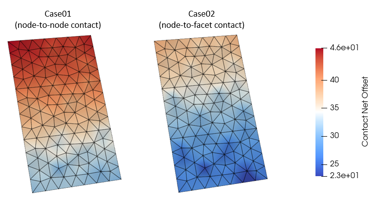
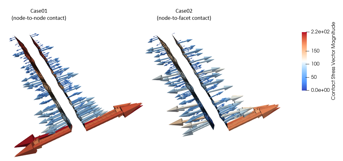
Below are some pictures showing the results at the end of the contact release stage. The end of such stage is chosen to discuss the results because a displacement reinitialisation is performed during the fourth stage and consequently the contact behaviour is less obvious at the end of the simulation.  From the results it can be seen that:


1.The node to node contact resulted in a larger contact offset.


2.The node to node contact resulted in a more homogeneous contact stress direction and magnitude distribution.


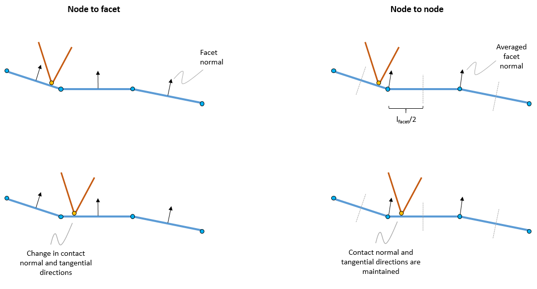
Both observations are a consequence of the fact that:


1.The node to node contact algorithm considers more homogeneous and smooth contact normal direction as for each node it uses the average of the connected facets normals.


2.For the amount of displacement there is no change in contact directions for any of the nodes in Case01 as the normal direction zone for each node extends to half of the connected facet length.


This is illustrated in the last figure.


Cont_003_002

Comparison of contact net offset for Case01 and Case02 at the end of the contact release stage.


Cont_003_004


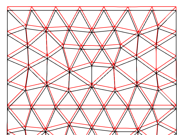
View of the fault mesh at the end of the contact release stage. Fault hanging wall (red) and fault foot wall (black).


Cont_003_003

Comparison of contact stress vectors for Case01 and Case02 at the end of the contact release stage.


Contact_data_003

Schematic of update in contact directions for node-to-facet (left) and node-to-node (right) algorithms