Step06 Forward Simulation
In the present workflow step tutorial page the key points specific to the forward simulation for TET models will be discussed in detail. Note minimal edits were required in the file Geol_003_Case01_Step06_fsim.dat (file edited for the present workflow step) relative to Geol_003_Case01_Step05_fsim.dat ("raw" file output in the previous step) to run the simulation. Those comprise:
1.To define Facies_definition data in the first stage
2.To define Spatial_state_set data to assign the facies values from the spatial grid to the model mesh for the pre-existing unit (note that the Include data loading the Spatial_grid with facies values is already present in the generated data file)
Note that in this case the simulation has been run for the mechanical field only (Porous_flow_type 5)
The data files for forward simulation are provided in Geol_003\Case01\Step06_Fsim\Data. Those files are:
1.Geol_003_Case01_Step04_rest_Fac_formationN.spat files containing the spatial grids with the facies distribution for formationN (output from restoration). Those will be used to assign the facies distribution during sedimentation.
2.Geol_003_Case01_Step05_fsim.geo initial geometry for the forward simulation
3.Geol_003_Case01_Step05_fsim_formationN.dat data file containing the part geometry definition used to drive the prescribed displacements for the stage in which formationN is deposited. The data files will be read by the main data file via Include data structure
4.Geol_003_Case01_Step05_fsim_formationN.sed data file containing the definition of the sedimentation horizon for formationN. The data files will be read by the main data file via Include data structure
5.Geol_003_Case01_Step06.mat file containing the material data for all the facies considered in the forward simulation.
6.Geol_003_Case01_Step06_fsim.dat main forward simulation data file. This is an edited version of the file output from the previous workflow step.
7.Geol_003_Case01_Step06_geostatic.dat datafile with geostatic data on a facies basis including compaction trends for the different facies.
The data defined to perform the forward simulation encompasses:
1.Geometry_data to read the Geol_003_Case01_Step05_fsim.geo file
2.Geometry_set data for the boundaries in the pre-existing formation
3.Group_data for the pre-existing formation with Porous_flow_type 5 (mechanical field with hydrostatic pressure assumption) and Group_control_data (mechanical being the only field active)
4.Material_data defined within the Geol_003_Case01_Step06.mat file (read via Include data structure)
5.Stratigraphy data:
a.Stratigraphy_definition and Stratigraphy_horizon data defining the full stratigraphy of the pre-existing geometry (which in the present case only includes formation01). Note that definition of the full stratigraphy is required for simulating sedimentation. The Basal_horizon keyword within Stratigraphy_definition is used to define the base of the model.
b.Stratigraphy_surface_load defining the boundary conditions for the top surface
6.Data required for modelling formations with facies distributions, i.e:
a.Facies_definition assigning material definitions to each facies number
b.The facies Spatial_grid containing the facies distribution for the initial geometry. This is defined within the Geol_003_Case01_Step04_rest_Fac_formation01.spat file (read via Include data structure)
c.Spatial_state_set to assign the facies numbers from the grid to the initial geometry model mesh
7.Gravity_data to apply the gravity load
8.Geostatic_data with compaction curves for each facies defined within the Geol_003_Case01_Step06_geostatic.dat file (read via Include data structure)
9.Damping_global_data defining damping to be used for the simulation
10. Mesh data:
a.Mesh_control_data and Unstructured_mesh_data, corresponding to the initial mesh generation, defined in the initial stage (compulsory to allow using adaptivity)
b.Adaptivity data (Adaptivity_control_data and Adaptivity_set_data) defined at the second stage (compulsory for sedimentation)
For each stage then we have:
11. Prescribed_boundary_data which assigns each Part_geometry_set boundary to its relative model boundary Geometry_set in order to prescribe the displacements following the specified Time_curve. Note that usually the base of the model is fully prescribed (displacement prescribed in all directions), whereas displacements in the side boundaries are prescribed in the direction normal to the part geometry (Lagrangian_algorithm set to "Normal").
12. Sedimentation_data with:
a.Deposited unit name defined via Stratigraphy_unit_name keyword
b.Assignment of sedimentation horizon (Sediment_horizon_name)
c.Duration of the sedimentation defining the time used to apply the gravity load to the deposited formation (starting from the start of the stage)
d.Material_name assigned to the deposited group and the name of the Material_file (generally definition of Material_file is not required if all materials used in the simulation have been previously defined)
e.Definition of the name of the Geostatic_data assigned to the deposited group. Note in the present case Geostatic_data is read from the corresponding file at every stage via Include data structure
f.Definition of of the name of the Spatial_grid (via Spatial_grid_facies) used to assign facies distribution to the deposited group. Note that the file containing the corresponding facies grid is read at each stage via Include data structure
13.Control_data for each stage (with data appropriate for a mechanical only simulation)
Some key data for the present forward simulation is discussed below.
Facies definition
|
Boundary displacements
In the forward models derived from TET restorations the boundary displacements are prescribed using Prescribed_boundary_data which assign to each model boundary Geometry_set its corresponding Part_geometry_set derived from restoration. Note the lack of Support_data in the forward simulation data file, as the displacements are prescribed using Prescribed_boundary_data isntead.
|
Sedimentation
At each sedimentation stage Sedimentation_data is defined in order to simulate the deposition of a new group / formation. Note that most keywords which are set in an identical manner for every stage could be defined in a Sedimentation_parameters data structure (not done in the present case) in the first stage. Note that some keywords in sedimentation data are edited relative to the default data obtained from restoration --> forward conversion.
|
Results
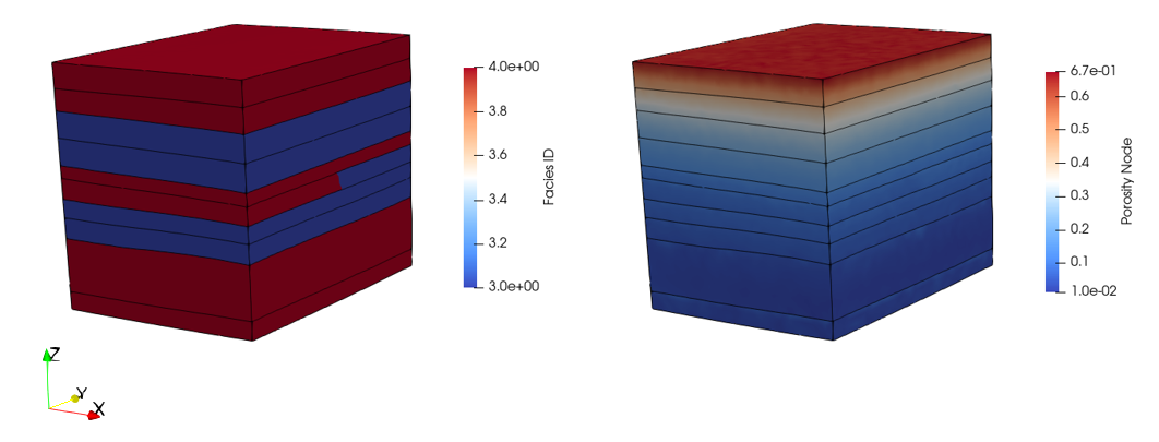
The results for the forward simulation are provided in Geol_003\Case01\Step06_Fsim\Results. Note that only the results for the last plot file output are provided.
By loading the file Geol_003_Case01_Step06_fsim_101.xmf in ParaView the results within the plot (.plt) file can be visualised.
Facies and porosity distribution at the end of the forward simulation.
|

