The data file for this example is located in Rest_002\Step2\Data.
In this example the data file to create the forward simulation is described. The file reads the .geo files generated during restoration (see the list of .geo files generated in the results section from Rest_002 Step1) and processes the data to generate the forward simulation input.
In addition to the data structures specific to restoration to forward conversion, data to be included into the generated forward model data file can also be defined in the present data file. For this example, we define:
▪Contact data for the fault
▪Geostatic data for the pre-existing and deposited formations
▪Adaptivity data
Data to be included in the generated forward model data file
Data required to define the forward model which is not directly related to processing restoration results for conversion is described here. This data will be automatically written to the generated forward model data file.
Contact data for the boundary conditions and the fault is defined.
Contact_surface
Data File
|
|
* Contact_surface NUM=1
Name "fault1_hgw"
Property_name "Fault"
Surface_interaction IDM=1
"fault1_ftw"
* Contact_surface NUM=2
Name "fault1_ftw"
Property_name "Fault"
Surface_interaction IDM=1
"fault1_hgw"
|
1Two Contact_surface data structures are defined for the fault hanging wall and fault footwall respectively.
|
Contact_set
Data File
|
|
* Contact_set NUM=1
Name "All"
Geometry_sets IDM=2
"fault1_ftw"
"fault1_hgw"
Property_name "Fault"
Global_update_frequency 1000
Field_factor 0.2
Buffer_factor 5.0
|
1A single contact set named "All" is defined. 2The list of included geometry sets is provided. These comprise the fault footwall and hanging wall. 3The default property assigned is named "Fault". 4Global contact search frequency is set to every 1000 mech steps. 5Field factor is set to 0.2. 6Buffer factor is set to 5.0.
|
Contact_global
Data File
|
|
* Contact_global NUM=1
Included_contact_sets IDM=1
"All"
All_geometry_flag 0
Corrective_step_flag 1
Factor_contact_time_step 0.75
|
1Contact_global data structure is defined to specify that defined contact set named "All" will be active in the forward simulation. 2The use of all external surfaces is OFF (All_geometry_flag = 0). 3A step to correct potential initial penetrations will be performed. 4The factor of critical time step for the contact is set to 0.75.
|
Contact properties
Data File
|
|
* Contact_property NUM=4
Name "Fault"
Field_dep_stiffness_model 1
Field_dep_stiffness_properties IDM=5
0.025
2.000
0.0
0.2
1.002
Compression_model 1
Compression_properties IDM=1
1000.0
Tangential_model 2
Tangential_properties IDM=2
500.0
1.0
Adhesion_model 1
Adhesion_properties IDM=1
500.0
|
1A contact property named "Fault" is defined. 2A penetration dependent stiffness model is used (see Cont_001 Case4 for full explanation). 3Compression, Tangential and Adhesion properties are defined.
|
|
Geostatic data to be incorporated in the forward simulation data file is defined.
Data File
|
|
* Geostatic_data NUM=1
Groups IDM=1
"formation1"
Porosity_spatial 1
K_value_x 0.7
K_value_z 0.7
Pore_pressure_distribution "Hydrostatic"
Time_curve "Step_ramp"
* Spatial_variation_definition NUM=1
Description "Porosity vs. Depth"
Type "Absolute"
Distribution "Depth_dependent"
Variation_assignment 1
* Spatial_variation_values NUM=1
Description "Normal Compaction Trend"
Time 0.0
Values_vs_depth IDM=35 JDM=2
0 179.3 ... 6097.4
0.48834 0.44717 ... 0.039523
* Geostatic_data NUM=2
Name "Sedimentation"
Porosity_spatial 1
K_value_x 0.7
K_value_z 0.7
Pore_pressure_distribution "Hydrostatic"
Time_curve "Step_ramp"
Deposition_flag 1
|
1Geostatic initialization is applied to the pre-existing formation in the forward model (in this case only first formation). 2Porosity is initialized with the data defined in the Spatial_variation_definition number 1. 3The Spatial_variation_definition is assigned the porosity trend in depth defined in the Spatial_variation_values number 1. 4Effective stress ratio values of 0.7 are defined for X and Z directions. 5The assigned time curve for the geostatic data is "Step_ramp". 6A second Geostatic_data structure is defined which is named "Sedimentation". This geostatic data will be assigned to the sedimentation data so that deposition is performed following the normal compaction trend rather that a constant porosity. In this way consistency between restoration and forward simulation is ensured. Definition of this second Geostatic_data structure is required because internally the Geostatic_data used for initialization (NUM=1) is removed once it has been used.
Note that geostatic data naming of "Sedimentation" is compulsory to allow assignment to sedimentation data and Deposition_flag must be set to 1.
|
|
Data File
|
|
* Adaptivity_control_data
Error_evaluation_frequency 1000
Default_element_sizes IDM=2
150
150
Maximum_remesh_frequency 10
List_of_remesh_sets IDM=1
1
* Adaptivity_set_data NUM=1
Group_numbers IDM=3
1 2 3
Deposition_flag 1
Distortion_area_data IDM=1
15
Element_sizes IDM=2
150
150
|
1An Adaptivity_control_data structure is defined. 2Remesh will be performed with a constant mesh size of 150 m. 3The error evaluation frequency to assess whether a remesh is required is set to every 1000 mech steps and the maximum error checks before a remesh is enforced is set to 10. 4A single Adaptivity_set_data for all groups is defined.
Note that at least one Adaptivity_set_data must be specified in conjunction with the definition of Adaptivity_control_data.
|
|
|
Restoration to Forward Simulation Conversion Data
Here the data used to process restoration results and create data for the forward model is discussed. It is noted that in the present case the displacements for the side boundaries and basal boundary will be performed via Prescribed_boundary_data. A special data structure (Basal_displacement) to allow contact on the fault and at the same time prescribe the displacements in the exposed portion of the hanging wall will be used.
Util_set_control_data
Data File
|
|
* Util_set_control_data
Target_number_time_steps 10000
Porous_flow_type 5
Element_size_bounds IDM=2
150
150
|
1Util_set_control_data structure is used to define: aA target number of time steps of 10000. bSet porous flow type for all groups. Note that groups are not needed to be defined as they are processed from the restoration output. cMesh size bounds - it will create Mesh_control_data and Unstructured_mesh_data data structures. |
|
Util_set_contact_data
Data File
|
|
* Util_set_contact_data
Fault_property_name "Fault"
Side_boundary_generation_flag 0
|
1Contact property named "Fault" is assigned to the basal boundary, side boundaries and faults by default (note that these contact properties were defined above). 2A Contact_set for side boundaries will not be generated (Side_boundary_generation_flag = 0). Note that in this case prescribed displacements on the side boundaries via Prescribed_boundary_data is adopted.
|
|
Util_set_material_data
Data File
|
|
* Util_set_material_data
Material_file "Shale.mat"
Unit_names IDM=3
"formation1"
"formation2"
"formation3"
Mdb_material_names IDM=3
"Shale_CF75"
"Shale_CF75"
"Shale_CF75"
|
1In Util_set_material_data materials are assigned to all pre-existing and deposited units. This will automatically assign the material data to the created sedimentation data. 2The material file name should be defined. 3The list of stratigraphy units and list of corresponding assigned materials should be defined. |
|
Util_basal_horizon
Data File
|
|
* Util_basal_horizon
Name "Basal_horizon"
Lines IDM=2
1 14 11
|
1Util_basal_horizon data structure is used to identify the basal boundary for the model. 2The list of lines that define the basal horizon must be specified. In this case it includes a portion of the fault hanging wall. 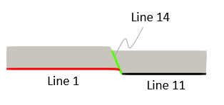
|
|
Util_set_boundary_data
Data File
|
|
* Util_set_boundary_data
Surface_applied_stress 0.1
Side_boundary_flag 3
Basal_boundary_flag 4
Side_boundary_geometry_sets IDM=2
"West"
"East"
Basal_boundary_geometry_sets IDM=2
"Basal_boundary_hgw"
"Basal_boundary_ftw"
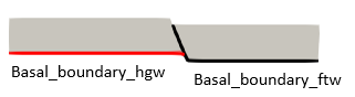
* Geometry_set NUM=100
Name "Basal_boundary_hgw"
Set_type r2f_conversion
Lines IDM=1
1
* Geometry_set NUM=101
Name "Basal_boundary_ftw"
Set_type r2f_conversion
Lines IDM=2
14 11
* Basal_displacement
Geometry_sets IDM=2
"Basal_boundary_hgw"
"Basal_boundary_ftw"
Overlap_distance 100
Output_level 3
|
1Util_set_boundary_data structure is used to define options and conditions for the model boundaries. 2A top surface stress of 0.1 MPa is defined (this will create a Stratigraphy_surface_load data structure). 3Side_boundary_flag is set to 3 (shape of side boundaries fully defined from restoration data). 4The geometry sets defining the side boundaries must be provided. 5Basal_boundary_flag is set to 4 (prescribed displacements via Prescribed_boundary_data with Basal_displacement to combine contact and prescribed displacements in the interior and exposed portions of the fault line 14 respectively. 6Identification of the geometry sets defining the basal boundary are listed within the Basal_boundary_geometry_sets keyword. Note that those geometry sets are defined here for usage with the Basal_displacement. 7The Geometry_set data for the basal boundaries are defined. Those geometry sets must be defined with Set_type "R2f_conversion" 8The Basal_displacement data structure is defined so that it will be included in each stage of the forward simulation data file. The geometry sets that define the basal horizon are identified. The Overlap_distance defines the distance of overlap for the different geometry sets for which the displacements will be prescribed (e.g. to ensure that the exposed portion of the fault line is supported and the material does not fall apart).
|
|
Util_fault_insertion
Data File
|
|
* Util_fault_insertion
Insertion_type "Split"
Faults IDM=1
"Fault1"
Deposition_flag 1
Deposition_length_fact 1.0
|
1Util_set_fault_insertion data structure is used to define that a split operation must be performed upon sedimentation of each new formation. 2Split operation will be performed for "Fault1". Note that by default all faults are considered for split operation if Faults keyword is not defined. 3Deposition_flag = 1 indicates that a split operation will be performed upon sedimentation of each formation. 4Deposition_length_fact = 1.0 indicates that the split will be performed considering the whole length of the fault path. Lower values will consider lower lengths of the total fault paths and therefore will result in a fault tip inside the split formation.
|
|
Util_forward_create
Data File
|
|
* Util_forward_create
Geometry_file_names 2
"Rest_002_Step1_formation3"
"Rest_002_Step1_formation2"
Analysis_file_name "Rest_002_Step3_Case01"
Basal_unit "formation1"
Pre_existing_top_unit "formation1"
Start_unit "formation2"
Pre_existing_geometry_flag 1
Pre_existing_sedimentation_flag 0
|
1In Util_forward_create data structure the .geo files containing the data from restoration that will be processed in order to define the forward model must be listed. 2The order must be provided in restoration order (from the youngest formation to the oldest one). 3Note that there is a limitation for which the forward simulation must start from the configuration at deposition of the first sedimented unit (with accommodation space already created). For that reason "Rest_002_Step1_formation1.geo" is not included in the list. 4The Analysis_file_name defines the name of the generated forward model data file. 5In Basal_unit the basal formation for the pre-existing sediments considered in the forward model must be specified. 6In Pre_existing_top_unit the top formation for the pre-existing sediments considered in the forward model must be specified. 7In Start_unit the first unit to be sedimented is specified. 8Pre_existing_geometry_flag = 1 indicates that pre-existing geometry will be present in the forward model. 9Pre_existing_sedimentation_flag = 0 indicates that geostatic initialization is performed prior to sedimentation of the Start_unit. As a result two stages for geostatic initialization will be created: aInitial stage assuming Elastic constitutive model. bSecond stage in which material will change to nonlinear material and stress will be released.
|
|
|
Results
The result files for the project are in directory: Rest_002\Step2\Results.
Files generated after execution of the forward create data file which will be used to run the forward model are:
1Rest_002_Step3_Case01.dat main data file for the forward model. 2Rest_002_Step3_Case01.geo geometry file containing the initial geometry for the forward model. 3Rest_002_Step3_Case01.GeoSumm file containing the geometry data summary contained in the .geo file. 4Rest_002_Step3_Case01_formation2.dat data file containing part geometry data which defines the boundary displacements during deposition of formation 2. 5Rest_002_Step3_Case01_formation2.sed file containing the sedimentation horizon for deposition of formation 2. 6Rest_002_Step3_Case01_formation3.dat data file containing part geometry data which defines the boundary displacements during deposition of formation 3. 7Rest_002_Step3_Case01_formation3.sed file containing the sedimentation horizon for deposition of formation 3. 8Rest_002_Step3_Case01_Pre_exist.dat data file containing part geometry data which provides support to the pre-existing geometry via either contact relationship or prescribed boundary data.
|
