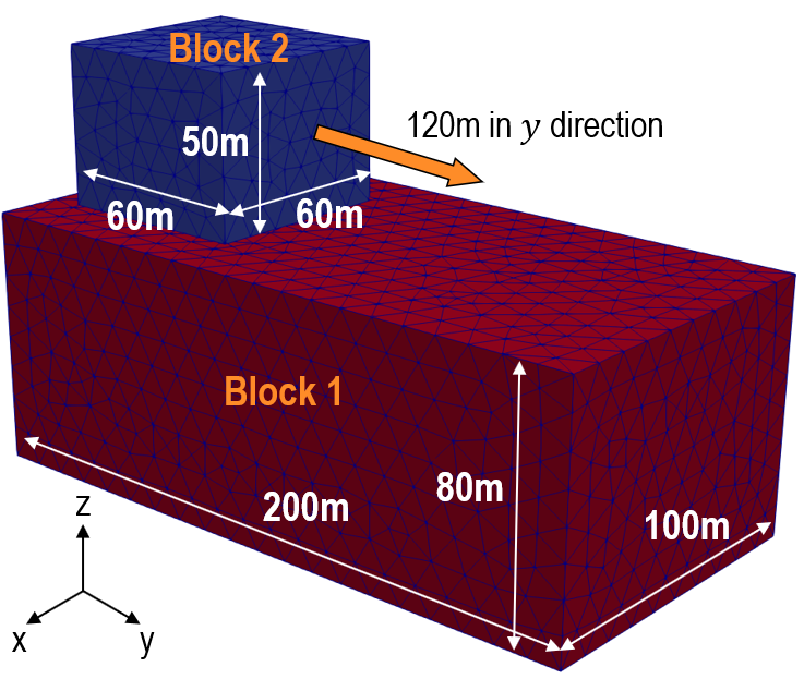
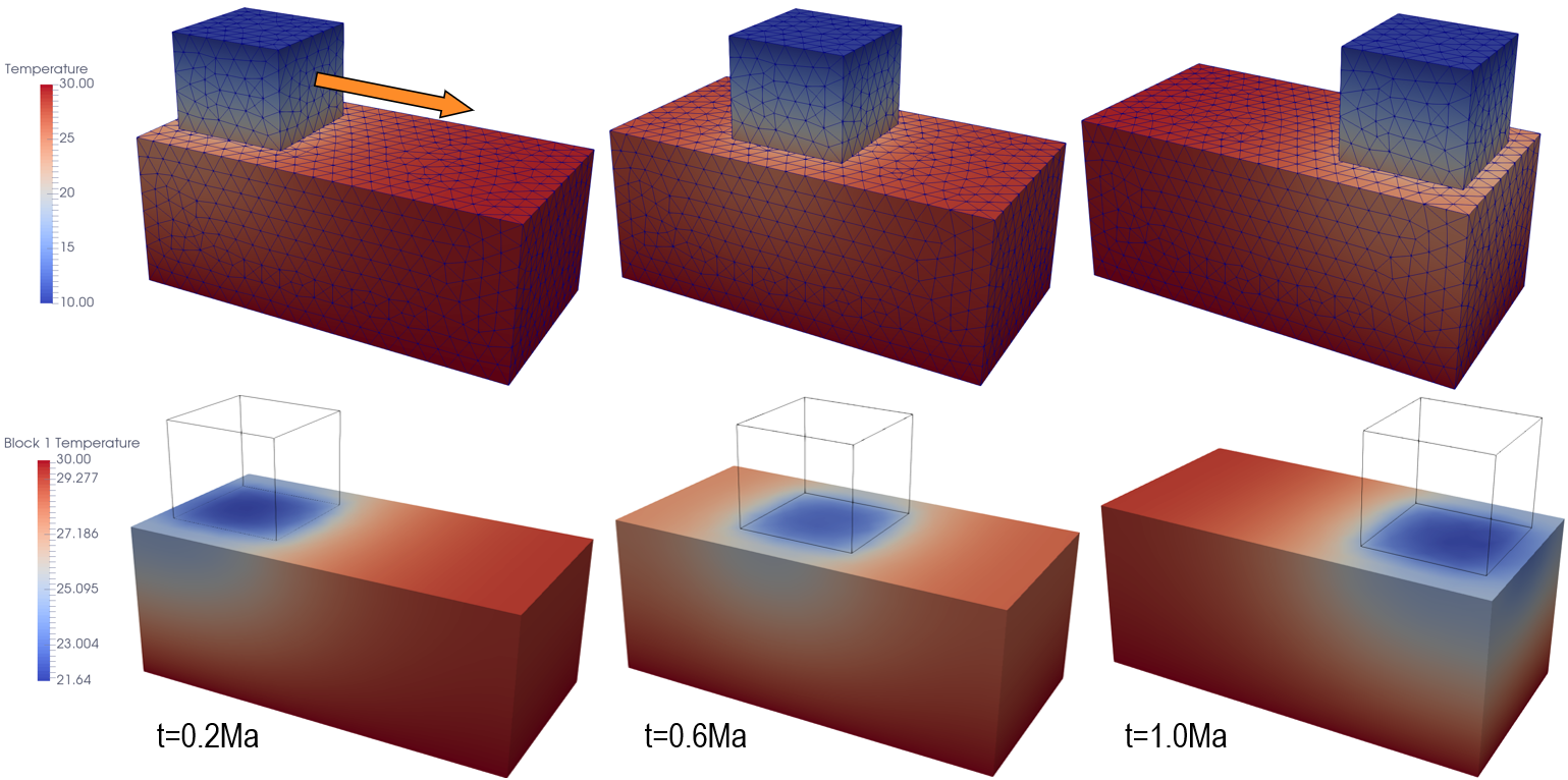
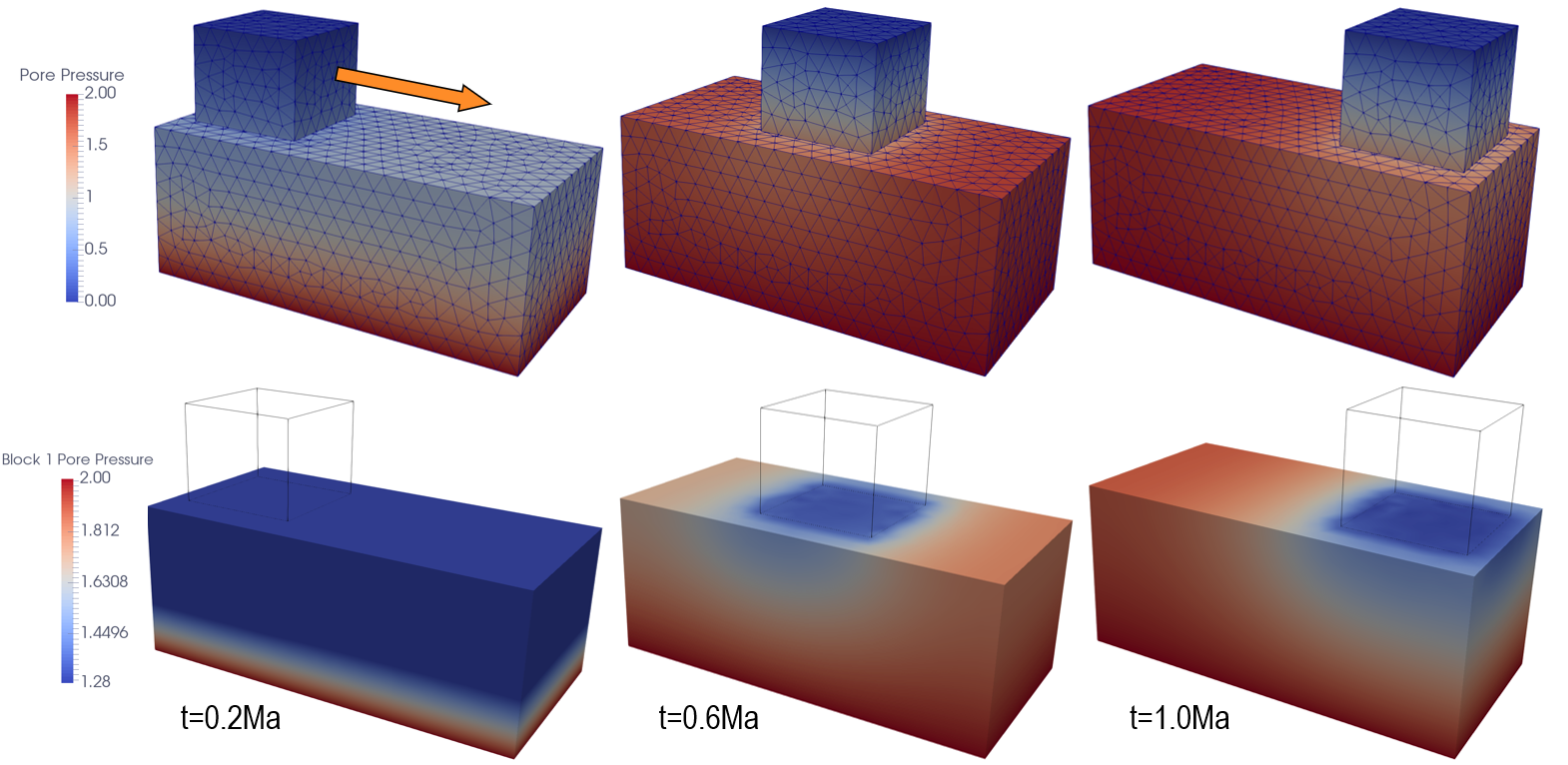
The data file for the project is: THM_001\Data\3D_THM_Block.dat. The basic data includes:
1Geometry_set groups multiple geometry entities under a convenient geometry set name, which will be used for stratigraphy definition, prescription of boundary condition, group data, etc. 2Stratigraphy_definition identifies the basal and top surface horizons using the prescribed geometry set. 3Stratigraphy_surface load defines the temperature (10 degC) and pore pressure (0MPa) at the top surface horizon. 4Stratitgraphy_basal_load defines the temperature (30 degC) and pore pressure (2MPa) at the basal horizon. 5Contact_set, Contact_property, Contact_global constitute contact data of fault surfaces. In particular, under Contact_property, flow and thermal models are prescribed. 6Group_control_data activates geomechanical, seepage and thermal fields for two groups. The latter is further defined under respective Group_data (e.g. element type, material name, geometry set, etc). 7Material_data and Fluid_properties both define the material properties of formation. 8Time_scaling_factors defines an optimal time step of 1E-4 Ma. 9Damping_global_data sets a global damping ratio of 2%. 10Support_data restricts the displacement of Base_block (Block 1) in all directions and allows the displacement of Top_block (Block 2) to be prescribed by the user. 11Global_loads defines the prescribed displacement (0, 120, 0)m on Top_block by following Time_curve_data. The loading is activated via Load_case_control_data. 12Mesh_control_data and Unstructured_mesh_data are used to generate unstructured meshes within the domain with a characteristic mesh size of 10m. 13Couple_control_data calls for incremental-type solution algorithm and undrained split scheme as well as defines the field names (i.e. geomechanical, porous flow, thermal) to be considered in the simulation. 14Control_data corresponding to two restoration stages is defined as follow: (a) Incremental solution algorithm (Type 4) (b) Maximum number of time steps of 1E8 (c) Duration of t=1.0 Ma (d) Initial time increment (Porous flow time step size) = 1E-2 Ma (e) Maximum number of iteration = 5000 (f) Factor of critical time step = 0.7 (g) Plot file output for every 20 coupling time steps
Geometry_set groups multiple geometry entities under a convenient geometry set name, which will be used for stratigraphy definition, prescription of boundary condition, group data, etc.
Data File
|
|
* Geometry_set NUM=1
Name "Base_block_fault"
Surfaces IDM=1
6
* Geometry_set NUM=2
Name "Top_block_fault"
Surfaces IDM=1
11
* Geometry_set NUM=3
.
.
.
* Geometry_set NUM=16
|
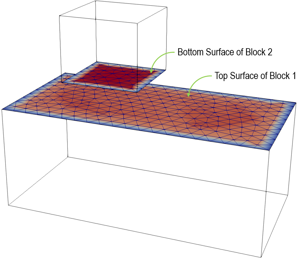
1For Geometry_set NUM=1, the top surface of Block 1 is recognised as Base_block_fault. 2For Geometry_set NUM=2, the bottom surface of Block 2 is recognised as Top_block_fault. 3Other geometry entities are assigned with corresponding geometry entities of Block 1 and 2.
|
|
Stratigraphy_definition defines the top and basal horizons via geometry set "Top_2" and "Bottom_1".
Data File
|
|
* Stratigraphy_definition
Top_surface_horizon "Top_2"
Basal_horizon "Bottom_1"
|
1"Top_2", which is the top surface of Block 2, is defined as the top surface horizon. 2"Bottom_1", which is the bottom surface of Block 1, is defined as the basal horizon. |
|
Stratigraphy_surface_load defines the temperature and pore pressure at the top surface horizon.
Data File
|
|
* Stratigraphy_surface_load
Pore_pressure_flag 1
Temperature_flag 1
Temperature 10
|
1Pore_pressure_flag = 1 indicates that the pore pressure at the top surface horizon is prescribed. In this case, the pore pressure at the horizon is 0MPa. 2Temperature_flag = 1 indicates that the temperature at the top surface horizon is prescribed at Temperature = 10 degC. |
|
Stratigraphy_basal_load defines the temperature and pore pressure at the basal horizon.
Data File
|
|
* Stratigraphy_basal_load
Pore_pressure 2.0
Temperature 30
|
The basal horizon is prescribed with Pore_pressure = 2.0MPa and Temperature = 30 degC.
|
|
In the following, contact data on the contact surfaces are defined through Contact_set, Contact_property, and Contact_global.
Contact_set
Data File
|
|
* Contact_set NUM=1
Name "All"
Geometry_sets IDM=2
"Top_block_fault"
"Base_block_fault"
Algorithm "Penalty"
Property_name "Block_contact"
Global_update_frequency 1000
|
1A single contact set, named "All", is defined. 2Geometry sets "Top_block_fault" and "Base_block_fault" are identified to define contact set. 3Penalty algorithm is selected. 4"Block_contact" property is assigned to the contact set. 5Global contact search frequency is set to every 1000 mechanical steps.
|
Contact_property
Data File
|
|
* Contact_property NUM=1
Name "Block_contact"
Compression_model 1
Compression_properties IDM=1
1000
Tangential_model 2
Tangential_properties IDM=2
/" "/ 10
/" "/ 0.1
Flow_model_normal 1
Flow_properties_normal IDM=2
/""/ 1E3
/""/ 1E3
Flow_model_tangential 1
Flow_properties_tangential IDM=1
/""/ 1E3
Thermal_model_normal 1
Thermal_properties_normal IDM=2
/""/ 1E14
/""/ 1E14
Contact_width 1.0
|
1A contact property named "Block_contact" is defined. 2Linear elastic compression model is assigned (compression model 1) with a normal compression stiffness of 1000 MPa. 3Coulomb friction model is assigned for tangential contact (tangential model 2) with a tangential stiffness of 10 MPa and a friction coefficient of 0.1. 4Contact normal fluid model with constant flow conductivity is defined via Flow_model_normal = 1. 5Contact normal fluid conductivity is prescribed via Flow_properties_normal. 6Contact tangential fluid model with constant flow conductivity is defined via Flow_model_tangential = 1. 7Contact tangential fluid conductivity is prescribed via Flow_properties_tangential. 8Contact normal heat model with constant heat conductivity is defined via Thermal_model_normal = 1. 9Contact normal heat conductivity is prescribed via Thermal_properties_normal. 10Contact_width is set at a value of 1.0m.
|
Contact_global
Data File
|
|
* Contact_global NUM=1
Included_contact_sets IDM=1
"All"
Contact_flow_flag 1
Contact_thermal_flag 1
|
1Contact_global data structure toggles Contact_set "All" as active. 2Fluid flow via contact surface is toggled active via Contact_flow_flag = 1. 3Heat flow via contact surface is toggled active via Contact_thermal_flag = 1. |
|
The Group_data is non-optional data structure, defining
1Group name 2Element type 3Material name assigned to each group 4Geometry set that defines the group 5Porous flow type
Data File
|
|
* Group_data NUM=1
Group_name "Top_block"
Element_type TET4V
Material_name "Block"
Geometry_set "Top_block"
Porous_flow_type 4
* Group_data NUM=2
Group_name "Base_block"
Element_type TET4V
Material_name "Block"
Geometry_set "Base_block"
Porous_flow_type 4
|
1Two groups, namely "Top_block" and "Base_block", are defined. 2The element type of all groups is set as TET4V, namely 4-Node 3-D Tetrahedral Average Volume Strain Element. 3All groups are assigned with material name, called "Block". 4Geometry_set assigns each Group_data with the corresponding geometry set. 5Porous_flow_type = 4 chooses coupled geomechanical/porous flow algorithm. |
|
The material properties for the material "Elastic" as well as its associated fluid properties are defined in the datafile.
Data File
|
|
* Material_data NUM=1
Material_name "Block"
Isotropic_Elastic_properties IDM=2
10E4 0.250
Porosity 0.3
Grain_density 2000
Grain_stiffness 50000
Biot_properties IDM=1
1.0
Permeability_type 1
Permeability 1E-22
Fluid_saturation 1.0
Singlephase_fluid 1
Grain_conductivity_type 1
Grain_conductivity 1E14
Grain_specific_heat 855
* Fluid_properties
Name "Water"
Fluid_type "Water"
Equation_state_type 0
Stiffness 2000.0
Density 1000.0
Viscosity_type 1
Viscosity 2.80E-23
Conductivity 1.89E+13 ! (N.m/Ma)/m/K 0.1 W/m/K
Specific_heat 4000
|
A single material is used for the simulation.
1The material is named "Block". 2Elastic properties (Young's modulus = 10E4 and Poisson's ratio = 0.25) are defined for the material. 3Porosity = 0.3 is assigned. 4Grain properties (density = 2000kg/m3 and stiffness) are defined. 5Biot constant = 1 is assumed. 6Constant permeability type is prescribed, with a value of 1E-22m2. 7Fluid saturation = 1and single-phase fluid are assumed. 8Isotropic thermal conductivity of solid grain is prescribed as 1E14 (J/Ma)/(m.K). 9Specific heat of solid grain is prescribed as 855J/kg/K. 10Fluid_properties is a non-optional data structure for Porous_flow_type = 4, defining the fluid type (i.e. "Water") as nearly incompressible (Equation_state_type = 0), stiffness (2000MPa), density (1000 kg/m3), constant viscosity (2.8E-23 MPa.Ma), thermal conductivity (1.89E13 [N.m/Ma]/m/K) and specific heat (4000 J/Kg/K). |
|
The mechanical step size is defined via Time_scaling_factors data structure. The Optimal_time_step keyword has been used. It is the most simple way of defining the mechanical time step size and is generally recommended. Using this method the mass scaling is computed automatically.
Data File
|
|
* Time_scaling_factors
Optimal_time_step 1E-04
|
An optimal time step of1·10-4 Ma is defined
|
|
The support data is used to define the fixity in X direction at pin location.
Data File
|
|
* Support_data
Displacement_codes IDM=3 JDM=1
1 1 1
Displacement_code_geom_set IDM=2
"Top_block"
"Base_block"
Displacement_code_geom_ass IDM=2
1 1
|
1One displacement code sets are defined. 2The displacements of "Top_block" and "Base_block" are prescribed. 3Note that the displacement of "Top_block" will be prescribed in Global_loads data structure. 4The displacement of "Base_block" is not prescribed in Global_loads, resulting in a stationary condition of the geometry.
|
|
This time curve is defined along with the prescription of displacement of "Top_block".
Data File
|
|
* Time_curve_data NUM=1
Time_curve IDM=3
0.0 0.2 1.0
Load_factor IDM=3
0.0 0.0 1.0
|
1A period of 0.2Ma will be allocated to the initialisation of pore pressure. 2The displacement of "Top_block" is prescribed with the duration from t = 0.2Ma to 1.0Ma.
|
|
The prescription of displacement of "Top_block" is defined here.
Data File
|
|
* Global_loads NUM=1
Prescribed_displacement IDM=3 JDM=1
// 0 120 0
Pres_displacement_geom_set IDM=1
"Top_block"
Pres_displacement_geom_ass IDM=1
1
|
1Geometry "Top_block" is assigned with a displacement of 120m in y-direction.
|
|
Global_loads NUM=1 is activated using this data structure.
Data File
|
|
* Load_case_control_data NUM=1
Loadcases IDM=1
1
Active_load_flags IDM=1
2
|
1The global load case NUM=1 associated with the prescribed displacement of "Top_block" is activated.
|
|
This data structure determines the mesh generation algorihm.
Data File
|
|
* Mesh_control_data NUM=1
Generation_algorithm 2
|
1Unstructured mesh will be generated.
|
|
This data structure determines the size of generated mesh.
Data File
|
|
* Unstructured_mesh_data NUM=1
Default_element_size 10
Element_size_bounds IDM=2
/Max. Element Size/ 10
/Min. Element Size/ 10
|
1The generated mesh size is invariably set as 10m.
|
|
This data structure determines the size of generated mesh.
Data File
|
|
* Coupled_control_data NUM=1
Field_names IDM=3
"Geomechanical"
"Porous_flow"
"Thermal"
Solution_algorithm "Incremental"
Volume_strain_coupling "Undrained"
|
1All field names involved in this problem are specified. 2Solution_algorithm = "Incremental" defines that the coupled field are solved in a staggered manner. 3The volumetric strain generated due to pore pressure is assumed to take place in an undrained condition.
|
|
Control_data corresponding to the simulation is specified.
Data File
|
|
* Control_data
Control_title "Step1"
Solution_algorithm 4
Maximum_number_time_steps 1E8
Termination_time 1.0
Displacement_norm_tolerance 0.1
Initial_time_increment 1E-2
Maximum_number_iterations 5000
Factor_critical_time_step 0.7
Output_frequency_plotfile 20
Screen_message_frequency 1
Output_frequency_iteration 1000
|
1Duration for control stage is set to 1.0 Ma is defined. 2The solution algorithm is set to number 4, i.e. Incremental form of the standard explicit dynamic solver . 3The maximum number of time steps is set to 1E8. 4The termination time is set as 1Ma. 5The tolerance for convergence based on the displacement norm in the incremental analysis is set to 0.1. 6The time step and maximum number for flow field is set to 1E-2. 7The maximum number of iteration is set to 5000. 8The factor critical time step is set to 0.7. 9A plot file is requested at a frequency of every 20 coupling steps. 0.2 Ma (Output_frequency_plotfile=0.2). 10Information will be displayed on the screen (command prompt) at each coupling step. 11The frequency for output of iteration data to the screen data in the incremental analysis is set to 1000. |
|
|


