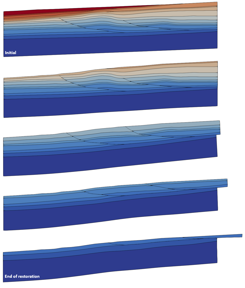
The basic data includes:
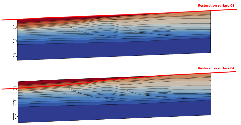
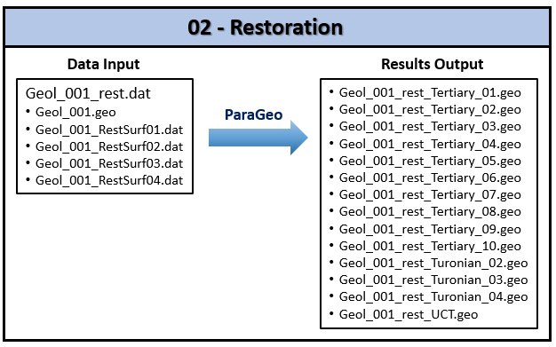
1.Geometry_data to read the .geo file containing the 2D geometry. 2.Group data for the sixteen formations which are assigned either "Elastic" or "Elastic_Stiff" properties using Group_control_data and Group_data data structures. 3.Geometry_set data that define the stratigraphy horizons, model boundaries, faults and detachments hanging walls and footwalls. 4.Stratigraphy_definition and Stratigraphy_horizon identifying the sixteen formations top horizons and basal horizon. 5.Two Material_data and one Fluid_properties data structures defining elastic material properties with vertical decompaction for the formations. The two base layers are defined stiffer elastic properties to maintain the detachment as flat as possible. 6.Geostatic_data to initialize the model to an average shale porosity NCT (Normal Compaction Trend) (Ewy et al. 2020) via Spatial_variation_definition and Spatial_variation_values data structures. 7. Fault_set data to identify the faults. 8.Contact data for the faults (Contact_global, Contact_set, Contact_surface and Contact_property). 9.Support data (Support_data) defining fixity in X direction at the West boundary. 10.Mesh control (Mesh_control_data) and unstructured mesh generation data (Unstructured_mesh_data) defining element mesh sizes between 50m and 80m. 11.Damping data (Damping_global_data) to define velocity damping of 0.02. 12.Output data (Output_data) to define the data for output to plot files. 13.Include data to read in the four part geometry data (Part_geometry_set, Part_line and Part_nodal_data) defining the four restoration surfaces. 14.Restoration_data defining the restoration operation, restoration top surface boundary conditions and assigning a part geometry as a restoration surface. 15.Control data (Control_data) for geostatic initialization stage defining: (a) Incremental solution algorithm (Type 1), (b) Factor of critical time step = 0.9, (c) Target number of time steps = 2000, (d) Maximum number of time steps of 1E7, (e) Duration of t = 1 Ma, (f) Screen message output every 500 mech steps, (g) Plot file output every 0.2 Ma, (h) Plot file output at the end of the stage, (i) Output of a restart file at the end of the stage. 16.Control data (Control_data) for the fourteen restoration stages (Tertiary_10 to Turonian_02) with the same control data as the geostatic initialization stage apart from: (a) Target number of time steps = 20000.
•Geometry_data, Group_data, Group_control_data and Geometry_set data can be copied from the Step 3 data file Geol_001_geom_Step3.dat and the following changes made: •Group_data for the oldest two layers ("Basement" and "Turonian_01") defined with the stiffer elastic material "Elastic_Stiff". •Four additional Geometry_set data structures are included for definition of "Fault_01_hgw_bas", "Fault_02_hgw_bas", "Detach_01_ftw" and "Detach_02_ftw". Note that these geometry sets will be used in the Contact_set and Contact_surface definitions.
Geometry data
Data File
|
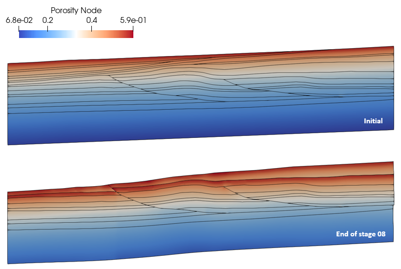
|
* Geometry_data
File_name "Geol_001"
File_format "hdf"
|
1.The geometry is read from the Geol_001.geo file with "HDF" format from the Step 1 workflow. Note that the geometry file name can be defined with or without an extension, however, the file itself must have the extension ".geo".
|
Group data
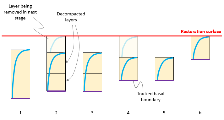
•The Group_data data structure is compulsory and defines the properties for each geometry group •The material assigned to the group. Note that the two oldest layers ("Basement" and "Turonian_01") which are below the detachment are defined with the stiffer elastic material "Elastic_Stiff". This facilitates recovery of the fault displacement and folding deformation while preventing excessive bending of the detachment.
Data File
|
|
* Group_data NUM=1
Group_name "Basement"
Element_type "Tpm3"
Material_name "Elastic_Stiff"
Porous_flow_type 5
Surfaces IDM=1
6
* Group_data NUM=2
Group_name "Turonian_01"
Element_type "Tpm3"
Material_name "Elastic_Stiff"
Porous_flow_type 5
Surfaces IDM=1
21
* Group_data NUM=3
Group_name "Turonian_02"
Element_type "Tpm3"
Material_name "Elastic"
Porous_flow_type 5
Surfaces IDM=3
5 17 18
(...)
* Group_data NUM=16
Group_name "Tertiary_10"
Element_type "Tpm3"
Material_name "Elastic"
Porous_flow_type 5
Surfaces IDM=1
11
|
1.A Group_data data structure is defined for each of the sixteen formations: a.Element_type is set to TPM3 (3 node 2D plane strain triangular element). b. The material assigned to all element groups is "Elastic" with the exception of the oldest two layers (Basement and Turonian_01) assigned "Elastic_Stiff". c.The simulation will be performed using the porous flow type number 5 (hydrostatic drained assumptions with vertical effective stress calculated using the buoyant density). d.The geometry entities (surfaces) defining each group are assigned.
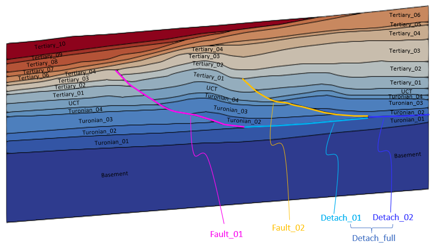
ParaGeo group data for individual formation layers (image scaled vertically by 2 to aid identification)
|
Group control data
•The Group_control_data data structure is compulsory and defines: 1.The group numbers of geometry groups in the problem, where each geometry group relates to a region with specific properties; e.g. regions with different material assignments, individual stratigraphy layers, etc. 2.Whether the group is active or inactive in the fields; i.e. geomechanical, porous flow, thermal, that are being solved.
Data File
|
|
* Group_control_data
Group_numbers IDM=16
1 2 3 4 5 6 7 8 9 10
11 12 13 14 15 16
Active_geomechanical_groups IDM=16
1 1 1 1 1 1 1 1 1 1
1 1 1 1 1 1
|
1.Group_control_data is used to define the geomechanical field as active for the sixteen formation groups.
|
Geometry set data
•Four additional Geometry_set data structures are included for definition of "Fault_01_hgw_bas", "Fault_02_hgw_bas", "Detach_01_ftw" and "Detach_02_ftw". These geometry sets will be used in the Contact_set and Contact_surface definitions.
Data File
|
|
* Geometry_set NUM=1
Name "Base"
Lines IDM=1
68
(...)
* Geometry_set NUM=29
Name "Fault_02_hgw"
Lines IDM=9
53 56 57 58 60 61 62 63 64
* Geometry_set NUM=30
Name "Fault_02_ftw"
Lines IDM=9
101 102 103 104 105 106 107 108 109
* Geometry_set NUM=31
Name "Fault_01_hgw_bas"
Lines IDM=14
1 16 42 43 44 45 46 47 48 49
50 51 52 40
* Geometry_set NUM=32
Name "Fault_02_hgw_bas"
Lines IDM=10
53 56 57 58 60 61 62 63 64 41
* Geometry_set NUM=33
Name "Detach_01_ftw"
Lines IDM=1
87
* Geometry_set NUM=34
Name "Detach_02_ftw"
Lines IDM=1
86
|
1.Thirty-four Geometry_set data structures are defined: a.Sixteen for the stratigraphy horizons. b.Three for the model boundaries (base, west and east). c.Two faults. d.Three detachments - two separate ones and one encompassing both detachments. e.Six for the three contact surfaces (Fault_01, Fault_02, Detach_full) hanging wall and footwall parts. f.Additional 4 for definition of "Fault_01_hgw_bas", "Fault_02_hgw_bas", "Detach_01_ftw" and "Detach_02_ftw" which will be used in the Contact_set and Contact_surface definitions (see picture below).
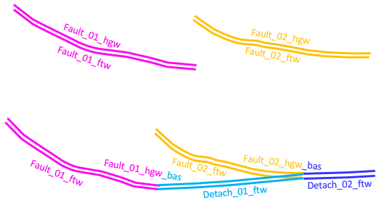
Geometry sets for faults and detachments hanging walls and footwalls
|
|
•Stratigraphy_definition and Stratigraphy_horizon data can be copied from the Step 3 data file Geol_001_geom_Step3.dat. •The stratigraphy is defined by: 1.Defining the existing stratigraphy layer depositional order and the group associated with each layer (via Stratigraphy_definition) from oldest to youngest. 2.Defining the topology of the top surface horizon for each stratigraphy layer including basal horizon (via Stratigraphy_horizon). •The stratigraphy is defined in a similar way to Mech_002 where there is a fuller description provided. •Note that in geomechanical restoration simulations initialization the definition of the stratigraphy is compulsory.
Data File
|
|
* Stratigraphy_definition
Units IDM=16
"Basement"
"Turonian_01"
"Turonian_02"
"Turonian_03"
"Turonian_04"
"UCT"
"Tertiary_01"
"Tertiary_02"
"Tertiary_03"
"Tertiary_04"
"Tertiary_05"
"Tertiary_06"
"Tertiary_07"
"Tertiary_08"
"Tertiary_09"
"Tertiary_10"
Basal_horizon "Base"
* Stratigraphy_horizon NUM=1
Name "Basement"
Lines IDM=1
6
(...)
* Stratigraphy_horizon NUM=17
Name "Base"
Lines IDM=1
68
|
1.Stratigraphy_definition defines the stratigraphy for a geomechanical analysis: a.Units lists the names identifying the top horizons for the sixteen formation layers present in the initial model in depositional order from oldest to youngest. b.Basal_horizon defines the Stratigraphy_horizon name of the basal horizon for the model "Base".
2.Seventeen Stratigraphy_horizon data structures are defined: a.Sixteen for the top surface of each stratigraphy layer. b.One for the basal horizon.
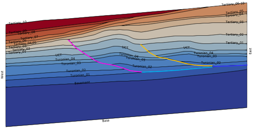
Stratigraphy horizons, model boundaries, faults and detachments (image scaled vertically by 2 to aid identification)
|
|
•The material properties for the material "Elastic" and "Elastic_Stiff" as well as its associated fluid properties are defined in the datafile. •Stiffer elastic properties are defined for the base and Turonian_01 layers so that the detachment can be maintained as flat as possible.
Data File
|
|
* Material_data NUM=1
Material_name "Elastic"
Units IDM=4
"MPa"
"m"
"Ma"
"Celsius"
Grain_density 2700
Grain_stiffness 30000
Porosity 0.60
Elastic_properties IDM=2
5000
0.20
Singlephase_fluid 1
Decompaction_Type 1
Decompaction_spatial 1
Decompaction_properties IDM=1
0.001
* Material_data NUM=2
Material_name "Elastic_Stiff"
(...)
Elastic_properties IDM=2
20000
0.20
(...)
Decompaction_properties IDM=1
0.001
* Fluid_properties NUM=1
Fluid_type "Water"
Density 1000
|
1.Two elastic materials are used for the simulation named "Elastic" and "Elastic_Stiff". 2.Elastic properties (Young's modulus = 5000 MPa and Poisson's ratio = 0.2) are defined for the "Elastic" material and stiffer properties (Young's modulus = 20000 MPa) defined for "Elastic_Stiff". 3.Grain properties (density and stiffness) are defined. 4.An arbitrary initial porosity of 0.6 is defined. 5.Fluid_properties number 1 is assigned to both materials. 6.Decompaction_type is set to 1 in order to decompact to a prescribed porosity trend. 7.Spatial_variation_values number 1 is assigned as the porosity trend to calculate decompaction (Decompaction_spatial = 1). 8.In Decompaction_properties, the maximum porosity increment between consecutive time steps is set to 0.001. 9.Definition of a fluid with its fluid density is compulsory for groups with Porous_flow_type = 5 defined in Group_data.
|
|
•Geostatic data is used to initialize the model with a specified porosity distribution via Spatial_variation_definition and Spatial_variation_values data structures. •Note that this porosity distribution will also be used to calculate decompaction.
Data File
|
|
* Geostatic_data NUM=1
Groups IDM=16
"Basement"
"Turonian_01"
"Turonian_02"
"Turonian_03"
"Turonian_04"
"UCT"
"Tertiary_01"
"Tertiary_02"
"Tertiary_03"
"Tertiary_04"
"Tertiary_05"
"Tertiary_06"
"Tertiary_07"
"Tertiary_08"
"Tertiary_09"
"Tertiary_10"
Porosity_spatial 1
* Spatial_variation_definition NUM=1
Description "Porosity vs. Depth"
Type "Absolute"
Distribution "Depth_dependent"
Variation_assignment 1
* Spatial_variation_values NUM=1
Description "Shale Average NCT"
Time 0.0
Values_vs_depth IDM=24 JDM=2
0 200 ... 4600
0.5890 0.4849 ... 0.0124
|
1.Geostatic initialization is applied to the 16 formations present in the model. 2.Porosity is initialized with the data defined in the Spatial_variation_definition number 1. 3.The Spatial_variation_definition is assigned the porosity trend according to depth defined in the Spatial_variation_values number 1 (see picture below).
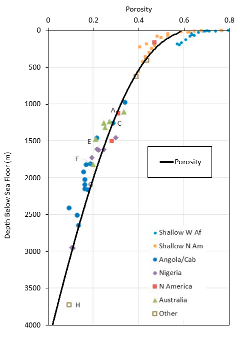
Normal compaction trend (decompaction trend) defined according to natural shale porosity data from samples collected in hydrostatic sediments from different parts of the world (Ewy et al. 2020)
|
|
The Fault_set data is used to identify geometry entities which form part of individual faults. This can be used to track fault geometries during restoration and insert faults later during the restoration-derived forward simulation.
Data File
|
|
* Fault_set NUM=1
Name "Fault_01"
Hangingwall_set "Fault_01_hgw"
Footwall_set "Fault_01_ftw"
Contact_sets IDM=1
"All"
* Fault_set NUM=2
Name "Fault_02"
Hangingwall_set "Fault_02_hgw"
Footwall_set "Fault_02_ftw"
Contact_sets IDM=1
"All"
|
1.Two fault sets are defined. 2.Names are defined for the fault set. 3.Geometry sets defining fault hanging wall and fault footwall are assigned. 4.Contact_sets named "All" is assigned to both fault sets.

Fault_set definitions for "Fault_01" and "Fault_02"
|
|
Data related to fault surfaces are defined through Contact_set, Contact_global, Contact_surface and Contact_property data structure to define frictionless contact surfaces for the faults and detachments.
Contact set data
Data File
|
|
* Contact_set NUM=1
Name "All"
Geometry_sets IDM=6
"Fault_01_hgw_bas"
"Fault_01_ftw"
"Fault_02_hgw_bas"
"Fault_02_ftw"
"Detach_01_ftw"
"Detach_02_ftw"
Algorithm "Penalty"
Property_name "Faults"
Global_update_frequency 1000
Field_factor 0.3
Buffer_factor 5.0
All_geometry_flag 0
|
1.A single contact set named "All" is defined. 2.Six geometry sets are included in the contact set definition. 3.Penalty algorithm is selected (this is currently the only option available). 4."Faults" property is assigned to the contact set. 5.Global contact search frequency is set to every 1000 mech steps. 6.Field factor is set to 0.3 so the maximum normal gap is defined as Gn = 0.3· lfacet where Gn is the normal gap and lfacet is the contact facet length. 7.The buffer factor for defining the buffer box size is set to 5.0 (the candidate target facets that can potentially establish a contact relationship with a given contactor node are those within the buffer box during a global search update). In this case the buffer box for a given node is an sphere centred at the node with radius R=5.0· lfacet where lfacet is the average length of the facets that terminate on the node. 8.Global geometry flag is set to OFF as included geometry sets are defined.
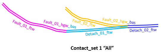
Contact_set definition "All"
|
Contact global data
Data File
|
|
* Contact_global NUM=1
Included_contact_sets IDM=1
"All"
|
1.Contact_global data structure is defined to specify that the defined contact set named "All" is active.
|
Contact surfaces data
Data File
|
|
* Contact_surface NUM=1
Name "Fault_01_hgw_bas"
Surface_interaction IDM=3
"Detach_01_ftw"
"Detach_02_ftw"
"Fault_01_ftw"
* Contact_surface NUM=2
Name "Fault_02_hgw_bas"
Surface_interaction IDM=2
"Detach_02_ftw"
"Fault_02_ftw"
* Contact_surface NUM=3
Name "Detach_01_ftw"
Surface_interaction IDM=1
"Fault_01_hgw_bas"
* Contact_surface NUM=4
Name "Detach_02_ftw"
Surface_interaction IDM=2
"Fault_01_hgw_bas"
"Fault_02_hgw_bas"
|
1.Four Contact_surface data structures define the contact surfaces that can interact with the defined surface.
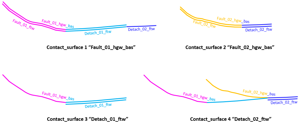
Definitions of contact surfaces that can interact with the defined surface
|
Contact property data
Data File
|
|
* Contact_property NUM=1
Name "Faults"
Compression_model 1
Compression_properties IDM=1
5000
Adhesion_model 1
Adhesion_properties IDM=1
5000
Tangential_model 2
Tangential_properties IDM=2
5000
0.0
|
1.A contact property named "Faults" is defined. 2.Linear elastic compression model is assigned (compression model 1) with a normal penalty stiffness of 5000 MPa. 3.Linear adhesion model is assigned (adhesion model 1) with a normal penalty stiffness of 5000 MPa. 4.Coulomb friction model is assigned for tangential contact (tangential model 2) with a tangential penalty stiffness of 5000 MPa and a friction coefficient of 0.0 (i.e. frictionless).
|
|
The support data is used to define the fixity in X direction at the West boundary.
Data File
|
|
* Support_data
Displacement_codes IDM=2 JDM=3
1 0
0 1
1 1
Displacement_code_geom_set IDM=1
"West"
Displacement_code_geom_ass IDM=1
1
|
1.Three displacement code sets are defined. 2.Displacement code set number 1 (fixity in X direction) is assigned to the West boundary.
|
|
An "unstructured mesh" with plane strain triangular elements with size between 50m and 80m is defined for this example.
Data File
|
|
* Mesh_control_data
Generation_algorithm 2
Mesh_generation_flag 0
* Unstructured_mesh_data
Default_element_size 80
Element_size_bounds IDM=2
80
50
|
1.The algorithm used for this simulation is set to 2 (i.e. unstructured mesh). 2.The mesh generation flag is set to 0 to perform the analysis after mesh generation (default). 3.The mesh element size is defined to be between 50m and 80m.
|
|
Data File
|
|
* Damping_global_data
Percentage_damping 0.02
|
1.Velocity damping of 0.02 is utilised.
|
|
Data File
|
|
* Output_data
Nodal_output_flags IDM=7
1
1
0
0
1
1
1
|
1.Nodal data for displacements, velocities, geomechanical fixities, external and internal forces are output.
|
|
|
