The forward simulation of this example adopts a workflow which sediments a new layer before geostatic initialization of the pre-existing formation. This is done in order to provide support and stability to the two fault "overhangs" on the pre-existing geometry during geostatic initialization (see picture below) which would otherwise 'collapse' without the support from the sediment layer. Consequently, the first two stages are single step analysis simply to establish the model data and geometries for the pre-existing formation and first sediment. Geostatic initialization of these two layers are then performed in stage 3 followed by stress release in stage 4. Sedimentation stages follow where the main process conditions are deposition of new layer, geostatic, prescribed basal boundary motion and side boundary displacements. Note that the first sediment is a special case where the sedimentation process is performed prior to geostatic initialization and the corresponding basal and side boundary displacements are performed separately after the stress release stage.

Image of example showing fault "overhangs" and basal boundaries in the pre-existing formation
The forward simulation data files are discussed in this manual page. Note that despite most of the data being automatically generated, the main data file for this Geol_001 example requires some editing to perform the forward simulation. The data described in the following sections will highlight the edited/added data as bold dark red text for easier reference. Note that restoration to forward simulation developments are ongoing to incorporate some of the edited data to be automatically generated. Copies of the original (automatically generated) data file and edited main data file are provided for reference.
The forward simulation data files are in: Geol_001\04_Forward_Sim\Data. The data comprises data files from 03 - Restoration to Forward and additional data files:
Data files from 03 - Restoration to Forward comprise:
1.Geol_001_FSim.dat - Main data file for the forward model. This requires editing.
2.Geol_001_FSim.geo - Geometry file containing the initial geometry for the forward model.
3.Geol_001_FSim_Pre_exist.dat - Data file containing part geometry data which provides support to the pre-existing geometry via either contact relationship or prescribed boundary data.
4.Data files containing part geometry data which defines boundary displacements during deposition of formation layers:
a.Geol_001_FSim_Tertiary_01.dat, ..., Geol_001_FSim_Tertiary_10.dat
b.Geol_001_FSim_Turonian_03.dat and Geol_001_FSim_Turonian_04.dat
c.Geol_001_FSim_UCT.dat
5.Data files containing the sedimentation horizons for the deposition of formation layers:
a.Geol_001_FSim_Tertiary_01.sed, ..., Geol_001_FSim_Tertiary_10.sed
b.Geol_001_FSim_Turonian_03.sed and Geol_001_FSim_Turonian_04.sed
c.Geol_001_FSim_UCT.sed
Additional data files include:
6.Shale_Average.mat - Material file including Material_data with permeabilities for all lithologies and Fluid_properties.
7.Geol_001_Element_Wedges.spat - Spatial grid data for "wedge" geometry elements requiring special treatment of material properties.
8.Geol_001_FSim_Turonian_03mod.dat - Copy of automatically generated Geol_001_FSim_Turonian_03.dat with all Part_nodal_update data structures removed.
Reference only data files are provided in: Geol_001\04_Forward_Sim\Data\Comparison_Edits_Main_Data to include:
9.Geol_001_FSim_original.dat - Renamed copy of original (automatically generated) main data file from 03 - Restoration to Forward workflow.
10.Geol_001_FSim_edited.dat - Renamed copy of edited main data file used to perform the forward simulation in Geol_001\04_Forward_Sim\Data folder.
The flowchart below summarises the data input and results output files involved in the forward simulation process. Files in blue text are additional files not directly generated from the restoration to forward process.
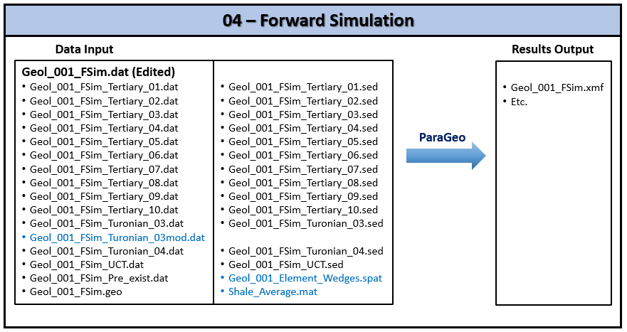
Summary flowchart of data input files and results output files in the forward simulation process
The pre-existing formation in this example contains "wedge" shaped basal boundary elements where the two faults intersect the base (shown in picture below). These are likely to cause numerical issues during the simulation if they become plastic, so special treatment is necessary to define these elements as elastic. In order to identify these "wedge" shaped basal boundary elements, a preliminary simulation as described below is needed to be performed prior to the main simulation.

Image identifying "wedged" shaped basal boundary elements in the pre-existing formation to be defined as elastic
Preliminary Simulation: Identification of "Wedge" Shaped Basal Boundary Elements
•Special treatment is to be applied to the "wedge" shaped basal boundary elements to define as elastic with spatial grid data for all sedimentation stages involving basal motion (stage 5 onwards).
•In order to identify the "wedge" shaped elements, a preliminary simulation run is to be performed up to the end of the stress release stage 4, prior to the main sedimentation stages.
oMake a copy of the main data file Geol_001_FSim.dat and rename as Geol_001_Elements_ID.dat.
oRemove all data after the Stage 4 Control_data.
oRun Geol_001_Elements_ID.dat data file.
oLoad up the results in ParaView and identify the "wedge" shaped elements to be included in the spatial grid data file .
•Create the Spatial_grid data file Geol_001_Element_Wedges.spat and include these elements with modified material properties set artificially high to stay elastic:
oPre-consolidation pressure "P_comc" = -40000 MPa
oTensile intercept "P_tenc" = 2000 MPa
oUnloading modulus "E_kappa" = 20
Main Forward Simulation:
The main forward simulation stages (total 17) and the operations performed for the six main stages are described below. Each stage is with duration of 1.0 Ma.
Stage 1: Establish Model Data and Pre-existing Sediment Data (1 Time Step)
•Model data including boundary support data (side and base) and pre-existing sediment data are defined.
•Gravity is applied.
•Solution control data is defined for 1 time step for the stage duration.
Stage 2: Sediment New Layer "Turonian_03" without Load Application (1 Time Step)
•Sediment new layer (Turonian_03) in 1 time step without performing any basal or side boundary displacements.
oTo achieve this, make a copy of the generated part geometry data file Geol_001_FSim_Turonian_03.dat and rename as Geol_001_FSim_Turonian_03mod.dat.
oIn Geol_001_FSim_Turonian_03mod.dat, remove all occurrences of the Part_nodal_update data structure which are required for basal boundary displacements.
•Solution control data is defined for 1 time step for the stage duration.
Stage 3: Perform Geostatic Initialization
•Geostatic initialization for the pre-existing sediment and first sediment is performed.
oConstitutive model is set as "Elastic".
oStress initialization type is set to "Standard".
•Geostatic data is defined with initial porosities following an NCT in depth via spatial data applied over the stage duration.
•Solution control data is set to perform 20000 time steps.
Stage 4: Perform Constitutive Stress Release
•Geostatic stress release is performed using a linear time curve over the stage duration.
oConstitutive model is switched from "Elastic" to "Standard".
oPoroelastic constants are set using end-of-step stresses.
oStress initialization type is set to "Standard" to ramp up from zero the final stresses from the end of the previous stage.
•Solution control data is set to perform 20000 time steps.
Stage 5: Apply Basal and Side Boundary Displacements corresponding to "Turonian_03" Layer
•Include spatial grid data from the preliminary simulation to apply special treatment for "wedge" shaped basal boundary elements to be elastic.
•Perform sedimentation of all layers with prescribed basal boundary displacements and side boundary displacements from the restoration stage. Note that the displacements are pinned on the west boundary.
•Solution control data is set to perform 20000 time steps.
Stages 6 - 17: Sedimentation of Deposition Layers with Basal and Side Boundary Displacements
•Perform sedimentation of all layers with prescribed basal boundary displacements and side boundary displacements from the restoration stage. Note that the displacements are pinned on the west boundary.
•Geostatic data for each of the sedimentation layers is defined with initial porosities following an NCT in depth via spatial data and applied over the stage duration.
•Solution control data is set to perform 20000 time steps.
Descriptions of the data file are provided in the following two sections:
•Model definition data
•Stage simulation process data - summary tables of the simulation stages and the data structures appearing in each are also presented.
Model Definition Data
The data defining the model which is unrelated to the stage simulation process data are described here. These data all appear prior to the stage 1 solution control data. Note that the data may not be described in the same order as it appears in the data file.
Data File
|
|
* Geometry_data
File_name Geol_001_FSim.geo
File_format hdf
|
1.Geometry_data is automatically generated to read in the geometry data from the generated .geo file.
|
|
Data File
|
|
* Units
Length "m"
Stress "MPa"
Time "Ma"
Temperature "Celsius"
|
1.Units data structure is automatically generated with definitions as specified in the forward create data file.
|
|
Stratigraphy data comprising Stratigraphy_definition, Stratigraphy_horizon, Stratigraphy_surface_load and Stratigraphy_smoothing data structures are automatically generated, however, some editing are required.
Stratigraphy_definition
Data File
|
|
* Stratigraphy_definition
Units IDM=1
"Turonian_02"
|
1.Stratigraphy_definition data of the pre-existing unit generated is edited to contain only the data shown.
|
Stratigraphy_horizon
Data File
|
|
* Stratigraphy_horizon NUM=2
Name "Basal_horizon"
Lines IDM=3
39 40 41
* Stratigraphy_horizon NUM=3
Name "Turonian_02"
Lines IDM=3
5 12 11
|
1.The Stratigraphy_horizon data sets generated is edited to comprise just the horizon sets relevant to the pre-existing unit as shown, i.e. basal and top horizons.
|
Stratigraphy_surface_load
Data File
|
|
* Stratigraphy_surface_load
Applied_stress 0.200000
Time_curve_stress "Step_scurve"
|
1.Stratigraphy_surface_load data structure is automatically generated to utilize time curve number 100 for the applied stress. This is edited to utilize the in-built "Step_scurve". 2.Applied_stress of 0.2 MPa is applied to the top surface horizon using this "Step_scurve" time curve.
|
Stratigraphy_smoothing
Data File
|
|
* Stratigraphy_smoothing
Active_flag -1
|
1.Stratigraphy_smoothing data generated will not be utilised and all keyword data generated are removed and defined with just Active_flag = -1. This will deactivate all stratigraphy smoothing and remove if defined. Note that stratigraphy smoothing of the top surface is automatically activated if sedimentation exists.
|
|
Numerous Geometry_set data structures are automatically generated. Only those sets containing definitions of lines for the pre-existing unit are to be included. To this end, we have removed the geometry set data structure for "Turonian_01" as our pre-existing unit is from "Turonian_02" onwards. We have also tidied up to remove all "empty" Geometry_set data structures (i.e. those without any Line definitions).
Data File
|
|
* Geometry_set NUM=35
Name "Basal_bound"
Set_type "r2f_conversion"
Lines IDM=1
39
(...)
* Geometry_set NUM=6
Name "East"
Lines IDM=1
76
(...)
* Geometry_set NUM=20
Name "Turonian_02"
Lines IDM=3
5 11 12
* Geometry_set NUM=24
Name "West"
Lines IDM=1
23
(...)
* Geometry_set NUM=31
Name "Fault_01_hgw_bas"
Lines IDM=3
42 43 40
* Geometry_set NUM=32
Name "Fault_02_hgw_bas"
Lines IDM=3
63 64 41
* Geometry_set NUM=36
Name "Basal_horizon"
Description "Basal Horizon"
Lines IDM=5
39 42 40 64 41
(...)
|
1.Only Geometry_set data structures containing definitions of lines for the pre-existing unit "Turonian_02" are included.
|
|
Group data comprising Group_data and Group_control_data data structures for the pre-existing formation are automatically generated. Stabilisation_parameter in Group_data is not required and hence will be removed.
Group_data
Data File
|
|
* Group_data NUM=1
Group_name "Turonian_02"
Element_type "Tpm3"
Material_name "Shale_avg"
Porous_flow_type 5
Surfaces IDM=3
5 17 18
|
1.Group_data defines the data for the pre-existing formation element group generated. 2.Note that Stabilisation_parameter keyword has been removed as it is not required. |
Group_control_data
Data File
|
|
* Group_control_data
Group_numbers IDM=1
1
Active_geomechanical_groups IDM=1
1
|
1.Group_control_data with the active group for pre-existing formation as generated. |
|
Data File
|
|
* Fault_set NUM=1
Name "Fault_01"
Footwall_set "Fault_01_ftw"
Hangingwall_set "Fault_01_hgw"
Insertion_type "Split"
Contact_sets IDM=1
"All"
Property_name "Faults"
* Fault_set NUM=2
Name "Fault_02"
Footwall_set "Fault_02_ftw"
Hangingwall_set "Fault_02_hgw"
Insertion_type "Split"
Contact_sets IDM=1
"All"
Property_name "Faults"
|
1. Fault_set data for the two faults present in the model is generated. 2.Contact property named "Faults" is assigned as specified in the forward create data file. |
|
Data File
|
|
* Material_data NUM=1
Name "Shale_avg"
Material_file "Shale_Average.mat"
|
1.Material data named "Shale_avg" is generated. 2.Material is read from the material file "Shale_Average.mat" specified in the forward create data file.
|
|
Damping_global_data is automatically generated for damping of the effective mean stress oscillations (Bulk_damping_model). This is changed to a mass proportional damping (Percentage_damping).
Data File
|
|
* Damping_global_data
Percentage_damping 0.02
|
1.Damping_global_data is defined to use 2% (0.02) mass proportional damping.
|
|
Gravity_data for the pre-existing formation is automatically generated with time curve NUM=100 and auto time scaling. We have edited the time curve data to use the internally generated "Step_scurve".
Data File
|
|
* Gravity_data
Gravity_constant 9.81000
Time_curve "Step_scurve"
|
1.Gravity_data is defined with gravity being applied following the internally generated "Step_scurve" for the pre-existing formation. 2.Note that for the deposited sediments, gravity loading is automatically applied internally in the ParaGeo code following the duration defined in the Sedimentation_data . Post stress release stage, gravity loading is always applied with an S-curve function over the sedimentation duration.
|
|
Contact data comprising Contact_set, Contact_global, Contact_surface and Contact_properties data structures are automatically generated. A total of eight Contact_surface data sets are generated, however, we will retain only the four sets which contains the Surface_interaction keyword and delete the remaining four sets.
Contact_set data
Data File
|
|
* Contact_set NUM=1
Name "All"
Contact_surfaces IDM=4
"Fault_01_hgw"
"Fault_01_ftw"
"Fault_02_hgw"
"Fault_02_ftw"
Global_update_frequency 1000
Property_name "Faults"
Field_factor 0.300000
Print_search 2
|
1.A single Contact_set named "All" is generated for the four contact surfaces in the pre-existing unit.
|
Contact_global data
Data File
|
|
* Contact_global
Included_contact_sets IDM=1
"All"
All_geometry_flag 0
Algorithm 1
|
1.Contact_global data structure is generated to specify that the defined contact set named "All" is active. |
Contact_surface data
Data File
|
|
* Contact_surface NUM=1
Name "Fault_01_hgw"
Property_name "Faults"
Surface_interaction IDM=1
"Fault_01_ftw"
Set_name "All"
* Contact_surface NUM=2
Name "Fault_02_hgw"
Property_name "Faults"
Surface_interaction IDM=1
"Fault_02_ftw"
Set_name "All"
* Contact_surface NUM=3
Name "Fault_01_ftw"
Property_name "Faults"
Surface_interaction IDM=1
"Fault_01_hgw"
Set_name "All"
* Contact_surface NUM=4
Name "Fault_02_ftw"
Property_name "Faults"
Surface_interaction IDM=1
"Fault_02_hgw"
Set_name "All"
|
1.The generated Contact_surface data structures defining the four contact surfaces and their surface interactions are utilized. |
Contact_property data
Data File
|
|
* Contact_property NUM=1
Name "Faults"
Compression_model 1
Compression_properties IDM=1
1000.00
Tangential_model 2
Tangential_properties IDM=2
1000.00 0.100000
Field_dep_stiffness_model 1
Field_dep_stiffness_properties IDM=5
0.250000E-01 2.00000 0.00000 0.200000 1.00200
|
1.A contact property named "Faults" is generated. 2.A penetration dependent stiffness contact model is utilised as defined in the forward create data file (see Cont_001 Case4 for full explanation of contact model).
|
|
Data File
|
|
* Mesh_control_data
Generation_algorithm 2
* Unstructured_mesh_data
Default_element_size 80.0000
Element_size_bounds IDM=2
80.0000 50.0000
|
1.Mesh data is generated as specified in the forward create data file.
|
|
Output_data data structure is added.
Data File
|
|
* Output_data
Nodal_output_flags IDM=7
1
1
0
0
1
1
1
|
1.An Output_data data structure defining the nodal data for output (0 - no output, 1 - output) to plot files is specified. This can help to reduce the size of the results plot files.
|
|
|
Summary Tables of Simulation Stages and Data Structures
Stages 1, 3 and 4: Pre-Existing, Initialization and Stress Release Stages
The table below summarises the data structures defined for the pre-existing, initialisation and stress release stages - "Y" signifies that it is defined, a greyed-out cell or "X" signifies non-defined and a greyed-out cell with "->" signifies that the last defined data is carried over to the current stage. Note that each stage duration is 1.0Ma.
|
|
Pre-Existing, Initialization and Stress Release Stages
|
Description
|
Data Structures
|
Stage 1
(Pre-exist)
|
Stage 3
(Initialization)
|
Stages 4
(Stress Release)
|
Geostatic control data
|
Geostatic_control_data
Time_curve_data (Num=101)
|
|
Y
X
|
Y
Y
|
Geostatic data (Pre-existing and Deposited Sediment)
|
Geostatic_data (Num=1)
Geostatic_data (Num=2)
Spatial_variation_definition (Num=1)
Spatial_variation_values (Num=1)
Time_curve_data (Num=100)
|
|
Y
|
|
Basal boundary displacement data
|
Include
Basal_displacement
Prescribed_boundary_data (Num=1)
Prescribed_boundary_data (Num=2)
Prescribed_boundary_data (Num=3)
Time_curve_data (Num=1)
|
Geol_001_FSim_Pre_exist.dat
Y
Y
Y
Y
Y
|
|
|
Support data for side boundaries
|
Support_data
|
Y
|
->
|
->
|
Adaptivity data
|
Adaptivity_control_data
Adaptivity_set_data
|
Y
|
->
|
->
|
Stage solution control data
|
Control_data
|
Y
|
Y
|
Y
|
|
Stage termination time
|
1
|
3
|
4
|
Stages 2, 5 - 17: Sedimentation Stages
The table below summarises the data structures defined for the sedimentation stages (each with duration of 1.0Ma) - "Y" signifies that it is defined, a greyed-out cell or "X" signifies non-defined and a greyed-out cell with "->" signifies that the last defined data is carried over to the current stage. Note that each sedimentation stage comprise sedimentation and basal + side motion, however, the start unit sedimentation of the Turonian_03 formation is split over two stages - stage 2 for sedimentation only and stage 5 for basal + side motion.
|
|
Sedimentation Stages
|
Description
|
Data Structures
|
Stage 2
(Turonian_03)
|
Stage 5
(Turonian_03)
|
Stages 6 - 10
(Turonian_04, ..., Tertiary_03)
|
Stages 11 - 17
(Tertiary_04 - Tertiary_10)
|
Sedimentation data
|
Include
Sedimentation_data
|
Geol_001_FSim_Turonian_03.sed
Y
|
|
Geol_001_FSim_UnitNames.sed
Y
|
Geol_001_FSim_UnitNames.sed
Y
|
Geostatic data (Deposited Sediments)
|
Geostatic_data (Num=2)
Spatial_variation_definition (Num=1)
Spatial_variation_values (Num=1)
Time_curve_data (Num=100)
|
Y
|
|
Y
|
Y
|
Fault insertion data
|
Fault_insertion
|
Y
|
|
Y
|
|
Basal boundary displacement data
|
Include
Basal_displacement
Prescribed_boundary_data (Num=1)
Prescribed_boundary_data (Num=2)
Prescribed_boundary_data (Num=3)
Time_curve_data (Num=1)
|
Geol_001_FSim_Turonian_03mod.dat
X
X
X
X
X
|
Geol_001_FSim_Turonian_03.dat
Y
Y
Y
Y
Y
|
Geol_001_FSim_UnitNames.dat
Y
Y
Y
Y
Y
|
Geol_001_FSim_UnitNames.dat
Y
Y
Y
Y
Y
|
Prescribed side boundary displacement load data
|
Load_case_control_data
Global_loads (Num=2)
Global_loads (Num=3)
Time_curve_data (Num=2)
Time_curve_data (Num=3)
|
|
Y
|
Y
|
Y
|
Support data for side boundaries
|
Support_data
|
->
|
->
|
Y
|
Y
|
Adaptivity data
|
Adaptivity_control_data
Adaptivity_set_data
|
->
|
Y
X
|
->
|
->
|
Special treatment data for "wedge" shaped basal boundary elements
|
Include
Spatial_state_set
Fault_smooth_set
|
|
Geol_001_Element_Wedges.spat
Y
Y
|
|
|
Stage solution control data
|
Control_data
|
Y
|
Y
|
Y
|
Y
|
|
Stage termination time
|
2
|
5
|
6 - 10
|
11 - 17
|
|
Stage Simulation Process Data
The process data for the various simulation stages are described here. Reference to the above summary tables is recommended.
Adaptivity data comprising Adaptivity_control_data and Adaptivity_set_data data structures are automatically generated as defined in the forward create data file. However, some editing is required as described below.
Data File
|
|
* Adaptivity_control_data
Error_evaluation_frequency 100000
Remesh_type "Global"
Remesh_sets IDM=1
1
Default_element_sizes IDM=2
80.0000 50.0000
Maximum_remesh_frequency 10
* Adaptivity_set_data
Groups IDM=2
1 2
Distortion_area_data IDM=1
15.0000
Region_type "All"
Deposition_flag 1
Element_sizes IDM=2
80.0000 50.0000
|
1.Adaptivity data is generated as specified in the forward create data file. 2.Adaptive remeshing is not required prior to basal motion, so the Adaptivity_control_data -> Error_evaluation_frequency number is intentionally set very high at 100000 to start with. 3.When basal motion is applied from stage 5 (Turonian_03), Adaptivity_control_data is respecified in this stage with the Error_evaluation_frequency set to 1000. This adaptivity data setting will then be carried through the remaining sedimentation stages to the end. Note that there is no need to re-define Adaptivity_set_data data structure. |
|
Support_data data structure for the side boundaries ("East" and "West") are automatically generated in the pre-existing stage and all the sedimentation stages.
Data File
|
|
* Support_data
Displacement_codes IDM=2 JDM=3
1 0
0 1
1 1
Displacement_code_geom_set IDM=2
"West"
"East"
Displacement_code_geom_ass IDM=2
1 1
|
1.Support_data is generated with fixities in the X direction assigned to the West and East boundaries.
|
|
Geostatic_control_data data structure is generated automatically in the initialization stage and stress release stage. Some editing is required to this data.
Geostatic_control_data (Initialization)
Data File
|
|
* Geostatic_control_data NUM=1
Stress_constitutive_model "Elastic"
Stress_initialisation_type "Standard"
|
1.This geostatic control data is generated automatically in the initialization stage.
|
Geostatic_control_data (Stress release)
Data File
|
|
* Geostatic_control_data NUM=1
Stress_constitutive_model "Standard"
Stress_initialisation_type "Standard"
Time_curve 101
Poroelastic_init_flag 1
* Time_curve_data NUM=101
Name "Release"
Time_curve IDM=2
3.00000 4.00000
Time_factor IDM=2
0.00000 1.00000
Curve_type 1
|
1.In the Geostatic_control_data for the stress release stage, a.Stress_initialisation_type is changed to "Standard", i.e. starting from zero stress, apply stress using data defined in the geostatic data structure. b.Time_curve number assigned is changed to101. c.Poroelastic_init_flag is set to 1 to use end-of-step stresses to set poroelasticity constants. 2.Time_curve_data (NUM=101) data structure with corresponding stage time interval is added to the stress release stage. a.Note that this time curve is only applicable in the geostatic stress release stage and the data structure if automatically generated for other stages can be removed.
|
|
Geostatic data is generated automatically as defined in the forward create data, however, requiring some edits. The data can be categorised into two parts:
1.Geostatic_data set 1 for pre-existing sediment defined for the initialization stage. 2.Geostatic_data set 2 for deposited sediments defined for the initialization and sedimentation stages. •The spatial variation data structures Spatial_variation_definition and Spatial_variation_values are defined in geostatic data sets 1 and 2 to initialize to the depth dependent porosity trend consistent with restoration. •Linear time curve NUM=100 is defined for both geostatic data sets.
Geostatic_data set 1 (Pre-existing sediment)
Data File
|
|
* Geostatic_data NUM=1
Groups IDM=1
"Turonian_02"
Pore_pressure_distribution "Hydrostatic"
Time_curve 100
K_value_x 0.700000
K_value_z 0.700000
Porosity_spatial 1
|
1.Geostatic data set 1 for the pre-existing sediment is automatically generated in the initialization stage 3. The data is initialized with the depth dependent porosity trend defined by the spatial variation data 1 and assigned time curve 100.
|
Geostatic_data set 2 (Deposited sediments)
Data File
|
|
* Geostatic_data NUM=2
Name "Sedimentation"
Pore_pressure_distribution "Hydrostatic"
Time_curve 100
K_value_x 0.700000
K_value_z 0.700000
Porosity_spatial 1
Deposition_flag 1
|
1.Geostatic data with the depth dependent porosity trend defined by the spatial variation data is automatically generated for the deposited sediments. This data is used to deposit pre-compacted sediments following the input porosity trend. In this way the volume of deposited sediment will be consistent with that of the corresponding restored formation in restoration. 2.The time curve for the geostatic set 2 for sedimentation is defined as curve number 100.
|
Spatial variation data set 1
Data File
|
|
* Spatial_variation_definition NUM=1
Description "Porosity vs. Depth"
Type "Absolute"
Distribution "Depth_dependent"
Variation_assignment 1
* Spatial_variation_values NUM=1
Description "Shale Average NCT"
Time 0.0
Values_vs_depth IDM=24 JDM=2
0 200 ... 4600
0.5890 0.4849 ... 0.0124
|
1.Spatial variation data for depth dependent porosities is automatically generated in conjunction with the geostatic data for the initialization and sedimentation stages.
|
Time_curve_data (NUM=100)
Data File
|
|
* Time_curve_data NUM=100
Time_curve IDM=2
0.00000 1.00000
Time_factor IDM=2
0.00000 1.00000
Curve_type 1
|
1.As part of the forward create data process, Time_curve_data (NUM=100) is automatically generated by default in all stages apart from the initialisation and stress release stages. We will change the Curve_type to 1 (linear). 2.Since we have adopted this curve to be used for the geostatic initialization stage 3, we will add the curve data to this stage. The time curve values are set to the start and end stage times, i.e. 2.0 and 3.0. 3.In stages where the curve data is generated but not used, the data can be removed. 4.When used in the geostatic data for the sedimentation stages, the ParaGeo code, internally, automatically scales the time curve values to the start and end times of the sedimentation stage. Hence, the values in the Time_curve keyword is inconsequential and can be left as the default generated values of 0.0 and 1.0. |
|
Sedimentation data comprising Include and Sedimentation_data data structures are defined for :
•Stage 2 - Sedimentation of start unit "Turonian_03" formation prior to performing geostatic initialization and stress release stages. •Stage 6 - 17 - Turonian_04 to Tertiary_10 sedimentation stages.
Include
Data File
|
|
* Include
Filename Geol_001_FSim_Turonian_03.sed
* Sedimentation_horizon NUM=1
Name "Restoration_surface"
Type "Facet"
Facet_topology IDM=2 JDM=208
1 2
2 3
.
.
208 209
Coordinates IDM=2 JDM=209
14373.0 3590.25
14452.9 3592.25
.
.
30928.1 4328.15
|
1.The appropriate named .sed file containing the corresponding sedimentation horizon data is generated automatically for each sedimentation stage. 2.In the .sed file, Sedimentation_horizon named "Restoration_surface" describes the isopach shape for the sediment to be deposited.
|
Sedimentation_data
Data File
|
|
* Sedimentation_data
Stratigraphy_unit_name "Turonian_03"
Sediment_horizon_name "Restoration_surface"
Duration 0.500000
Material_name "Shale_avg"
Material_file "Shale_Average.mat"
Geostatic_set_name "Sedimentation"
Isopach_option_flag 0
Sedimentation_algorithm 1
Minimum_thickness 50
|
1.Sedimentation_data for each sedimentation stage is automatically generated from restoration with the following specified: a.Name of the formation, e.g. "Turonian_03". b.Isopach sedimentation algorithm. c.Assignment of the isopach sedimentation horizon (named "Restoration_surface"). d.Duration of the sedimentation is set as 0.5 (default). Note that this duration will also be used internally to automatically apply gravity load to the sediment following an S-curve. e.Material and material file for the new sediment, e.g. "Shale_avg" material data is read from Shale_Average.mat file. f.Assignment of the geostatic data named "Sedimentation". a.Sedimentation algorithm 1 (always = 1). 2.A Minimum_thickness keyword is added to define a minimum thickness threshold of 50m for each deposited layer below which no sediment will be deposited. |
|
Fault_insertion data is automatically generated for all sedimentation stages, however, the data structure needs to be defined only for the relevant sedimentation stages (refer image below) and must be removed from the remaining stages. Some editing is also required to the generated data to apply split only to the relevant fault(s) plus to include additional split data. The image below shows "Fault_01" requires fault split up to the Tertiary_03 sediment and "Fault_02" requires fault split up to the Tertiary_01 sediment. Fault_insertion data is to be defined for the following sedimentation stages:
•Stage 2 - First sediment Turonian_03 unit. •Stages 6 - 10: Sedimentation stages for Turonian_04 - Tertiary_03 units.
Data File
|
|
* Fault_insertion
Insertion_type "Split"
Units IDM=2
"Turonian_04"
"Turonian_03"
Faults IDM=2
"Fault_01"
"Fault_02"
Tip_length_factors IDM=2
0.5 0.5
|
1.Fault_insertion defines data for each sedimentation stage. Refer image below of defined geometry for restoration to identify faults to be inserted for each of the sedimentation layers. 2.Insertion_type is set to "Split". 3.Units define the names of the new sedimented unit and the current sedimented unit (e.g. Turonian_04 and Turonian_03 shown here). 4.Faults define the Fault_set name(s) to be split. a."Fault_01" and "Fault_02" are to be split for Turonian_03, Turonian_04, UCT and Tertiary_01 layers. b.Only "Fault_01" is to be split for the Tertiary_01 and Tertiary_02 layers. c.No faults are to be split for the remaining Tertiary_03 - Tertiary_10 layers. 5.Add Tip_length_factors keyword for the defined faults and set as 0.5, i.e. the percentage of the top formation to be penetrated by each fault is half.
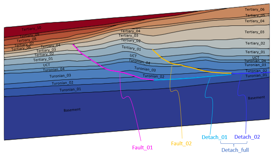
Defined geometry for restoration showing formation layers and faults (image scaled vertically by 2 to aid identification)
|
|
Basal boundary displacement data comprising Include, Basal_displacement, Prescribed_boundary_data and associated Time_curve_data data structures are defined for :
•Stage 1 - Pre-existing sediment to provide initial basal fixities. •Stage 5 - 17 - Turonian_03 to Tertiary_10 sedimentation stages to define prescribed basal boundary motion via a linear time curve. The relevant basal boundary displacement data structures are generated automatically in the above stages, albeit with some editing required and inclusion of the Basal_displacement data structure.
Include
Data File
|
|
* Include
Filename Geol_001_FSim_Pre_exist.dat
|
1.An Include data structure stating that file Geol_001_FSim_Pre_exist.dat (file containing part geometry data for the boundary support) must be read is generated. 2.Note that at each simulation stage after "Stress Release" stage, one Include data structure pointing to the data file containing the basal boundary conditions associated with the stage will be generated, e.g. at next stage after "Stress Release", an Include data structure pointing to Geol_001_FSim_Turonian_03.dat is generated. |
Basal_displacement
Data File
|
|
* Basal_displacement
Geometry_sets IDM=3
"Basal_bound"
"Fault_01_hgw_bas"
"Fault_02_hgw_bas"
Output_level 3
|
1.Basal_displacement data structure is added to identify the specialized basal boundary displacements in forward simulations with faults, so that the exposed nodes of the basal boundary will be prescribed displacement whereas the nodes of the basal boundary that are in a fault will be free. For full description of this data structure, refer to the reference manual Basal_displacement. |
Prescribed_boundary_data
Data File
|
|
* Prescribed_boundary_data NUM=1
Part_geometry_set "Basal_bound_pg"
Geometry_set "Basal_bound"
Time_curve 1
Boundary_type "Lagrangian"
Edge_element_fixity_flags IDM=2
0
1
* Prescribed_boundary_data NUM=2
Part_geometry_set "Fault_01_hgw_bas_pg"
Geometry_set "Fault_01_hgw_bas"
Time_curve 1
Boundary_type "Lagrangian"
Edge_element_fixity_flags IDM=2
0
1
* Prescribed_boundary_data NUM=3
Part_geometry_set "Fault_02_hgw_bas_pg"
Geometry_set "Fault_02_hgw_bas"
Time_curve 1
Boundary_type "Lagrangian"
|
1.Three Prescribed_boundary_data are generated for the three geometry sets associated with the basal boundary displacement. This data structure is generated from the specification in Util_set_boundary_data in the forward create data file. a.A "Lagrangian" boundary surface type is defined where the mesh is fixed to the boundary. b.Edge_element_fixity_flags keyword is added to define the start and end facets of the green and red basal boundary geometry sets (see picture below). The two "wedge" shaped end facets of these two boundaries are prescribed special treatment to make the adjacent element elastic defined with a spatial grid (described later). c.Time_curve is generated automatically for the sedimentation stages 5 - 17. It is not required for the pre-existing sediment stage and is not defined as such.
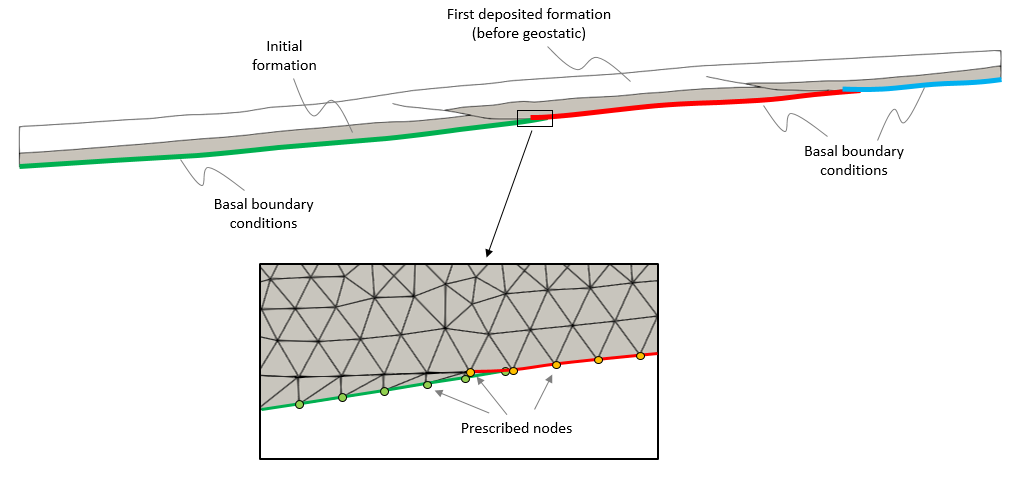
Specialized basal boundary displacements with prescribed and free nodes
|
Time_curve_data
Data File
|
|
* Time_curve_data NUM=1
Time_curve IDM=2
4.0 5.0
Time_factor IDM=2
0.0 1.0
Curve_type 1
|
1.Time_curve_data (NUM=1) associated with the Prescribed_boundary_data data structure for the sedimentation stages defines a linear time curve for the basal motion. The time interval must correlate with the individual stage time, e.g. for stage 5 "Turonian_03" sedimentation, the time interval defined must be between t=4 and t=5.
|
|
As described previously, special treatment is to be applied to the "wedge" shaped basal boundary elements to define as elastic with spatial grid data for all sedimentation stages involving basal motion (i.e. stage 5 onwards). The spatial grid data identifying the relevant elements and their numbering have previously been identified in the preliminary simulation carried out. Their inclusion into the main forward simulation data file is now described.
Include
Data File
|
|
* Include
Filename "Geol_001_Element_Wedges.spat"
* Spatial_grid
Number 2
Name "Hardening"
Type "Element"
Element_variables IDM=3
"P_comc"
"P_tenc"
"E_kappa"
Element_numbers IDM=27
1
(...)
1436
Element_values IDM=3 JDM=27
-40000 2000 20.0
(...)
-40000 2000 20.0
|
1.An Include data structure is added to read in Geol_001_Element_Wedges.spat file containing the "wedge" shaped element numbers with following modified material properties set artificially high to stay elastic: •Pre-consolidation pressure "P_comc" = -40000 MPa •Tensile intercept "P_tenc" = 2000 MPa •Unloading modulus "E_kappa" = 20
|
Spatial_state_set data
Data File
|
|
* Spatial_state_set
Spatial_grid "Hardening"
Groups IDM=1
"Turonian_02"
State_variables IDM=3
"P_comc"
"P_tenc"
"E_kappa
|
1.A Spatial_stage_set data structure is added to define the state variables for assignment of spatial variations to the pre-existing element group "Turonian_02".
|
Fault_smooth_set data
Data File
|
|
* Fault_smooth_set
Name "FSmooth"
Fault_names IDM=2
"Fault_01"
"Fault_02"
Max_facet_angle 10
Update_frequency 100
|
1. Fault_smooth_set data structure is added to smooth out any fault kink shapes which may develop to avoid potential numerical issues. 2.The fault shape is smoothed based on a maximum imposed angle of 10º between adjacent facets as defined in Max_facet_angle. 3.The fault smoothing operation is performed every 100 steps as defined in Update_frequency.
|
|
The side boundaries ("East" and "West") are pinned on the "West" boundary (i.e. zero prescribed displacements) and prescribed displacements from the restoration on the "East" boundary. These side boundary displacement load data are defined via Global_loads, Time_curve_data and Load_case_control_data data structures.
•The prescribed side boundary displacements are defined for all sedimentation from stages 5 (Turonian_03) to 17 (Tertiary_10). •Note that the Support_data associated with this side boundary displacement loading has already been defined in stage 1 and the same fixity condition is carried through to the end.
Data File
|
|
* Global_loads NUM=2
Prescribed_displacement IDM=2 JDM=1
1.00000 0.00000
Pres_displacement_geom_set IDM=1
"West"
Pres_displacement_geom_ass IDM=1
1
* Global_loads NUM=3
Prescribed_displacement IDM=2 JDM=1
1.00000 0.00000
Pres_displacement_geom_set IDM=1
"East"
Pres_displacement_geom_ass IDM=1
1
|
1.Global_loads (NUM=2 and NUM=3) with associated Time_curve_data defines the prescribed displacements on the "West" and "East" boundaries respectively. The displacement values are generated automatically from the forward create data. a.The "West" boundary time factor is set as 0 to define the pinned boundary condition. b.The "East" boundary time factor displacement values are from restoration and generated automatically. c.The time interval for the time curve increments must correlate with the individual stage time.
|
Load_case_control_data
Data File
|
|
* Load_case_control_data
Loadcases IDM=2
2 3
Active_load_flags IDM=2
1 1
|
1.Load_case_control_data defines the two displacement load cases as active.
|
Time_curve_data
Data File
|
|
* Time_curve_data NUM=2
Time_curve IDM=6
4.00000 4.200000 4.400000 4.600000 4.800000
5.00000
Time_factor IDM=6
0.00000 0.00000 0.00000 0.00000 0.00000
0.00000
Curve_type 1
* Time_curve_data NUM=3
Time_curve IDM=6
4.00000 4.200000 4.400000 4.600000 4.800000
5.00000
Time_factor IDM=6
0.00000 -65.8943 -131.434 -198.871 -265.753
-334.577
Curve_type 1
|
1.Time_curve_data shown here are for stage 5 Turonian_03 sedimentation where the time interval for the increments defined must be changed to the relevant times for the stage, i.e. for this stage, between t=4 and t=5. For stage 6 sedimentation, the time interval defined must be between t=5 and t=6, and so on.
|
|
Two sets of Control_data data structure with individual Control_title name are automatically generated for each simulation stage. We will add the keyword Target_number_time_steps to both these control data sets and set Duration to 1.0 Ma for all stages:
•Control_data set 1: Defined with Maximum_number_time_steps = 1 for the first two simulation stages (pre-existing and start unit sediment before geostatic initialization). Target_number_time_steps = 1 is added to this stage. •Control_data set 2: Defined with Maximum_number_time_steps = 10000000 for all other simulation stages. Target_number_time_steps = 20000 is added to this stage.
Control_data set 1 (Pre-existing and start unit sediment)
Data File
|
|
* Control_data
Control_title "Pre_exist"
Solution_algorithm 1
Factor_critical_time_step 0.5
Target_number_time_steps 1
Maximum_number_time_steps 1
Duration 1.0
Output_frequency_plotfile -1
Screen_message_frequency 1000
Output_frequency_restart -1
|
1.Control_data is generated with Maximum_number_time_steps = 1. 2.Keyword Target_number_time_steps = 1 is added in order to perform only one analysis time step in the current stage with duration of 1.0 Ma.
|
Control_data set 2 (Other)
Data File
|
|
* Control_data
Control_title "Stress Release"
Solution_algorithm 1
Minimum_time_step 0.100000E-07
Factor_critical_time_step 0.500000
Target_number_time_steps 20000
Maximum_number_time_steps 10000000
Duration 1.00000
Output_frequency_plotfile -1
Output_time_plotfile 0.200000
Screen_message_frequency 1000
Output_frequency_restart -1
|
1.Control_data is generated with Maximum_number_time_steps = 10000000. 2.Keyword Target_number_time_steps = 20000 is added to define the number of mechanical time steps to be used to solve the current simulation stage. 3.Duration is set to 1.0 Ma for all stages. |
|
|
Results
The result files for the project are in directory: Geol_001\04_Forward_Sim\Results.
The figure below shows the evolution of the generated forward model.
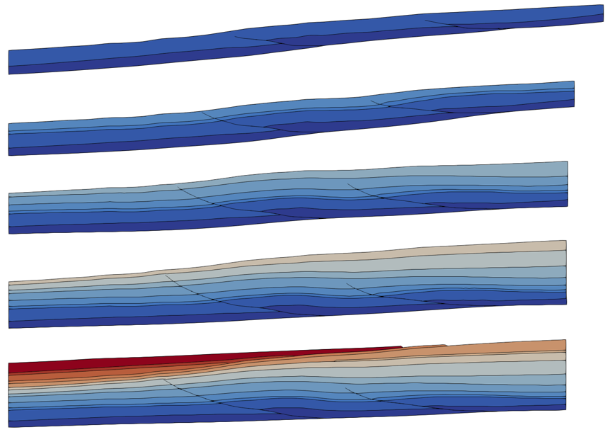
Evolution of generated forward model
A comparison of the target structure and the predicted forward model structure show very good correlation achieved.
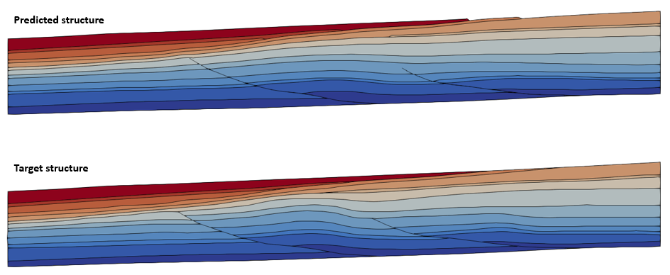
Comparison of target structure and predicted forward model structure
The figures below show the distribution of strain and stress in the XX and YY directions in the generated forward model. Maximum horizontal strains are observed in the hanging walls of the faults. Very high compressive stresses are located at the base of the hanging wall of fault_01.
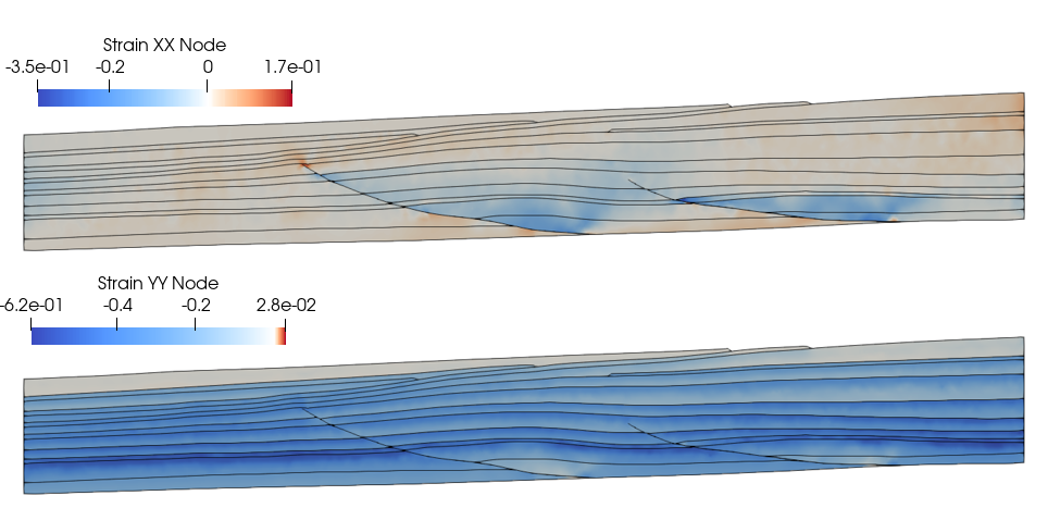
Distribution of Strain in XX and YY directions in generated forward model
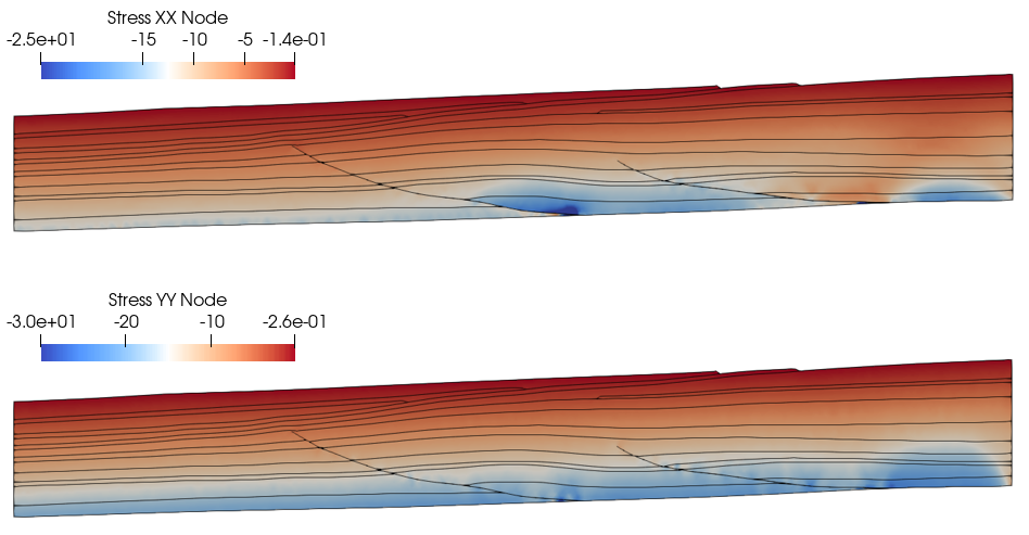
Distribution of Stress in XX and YY directions in generated forward model
The porosity distribution in the generated forward model follows that of the normal compaction trend defined.

Porosity distribution in generated forward model - NCT defined according to natural shale porosity data from samples collected in hydrostatic sediments from different parts of the world (Ewy et al. 2020)
The figure below shows the displacements in X and Y in the generated forward model.
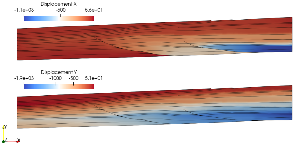
Displacements in X and Y in generated forward model
The figure below shows the contact net offset (or fault slip) in the generated forward model.

Contact net offset (fault slip) in generated forward model
|


