MEM and Wellbore modelling

Contents
INDEX
Title |
Analysis Type - Features List / Utility |
Model |
Workflow for Material Earth Models (MEMs) |
||
Mechanical (3D) / Coupled HM (3D) |
|
|
|
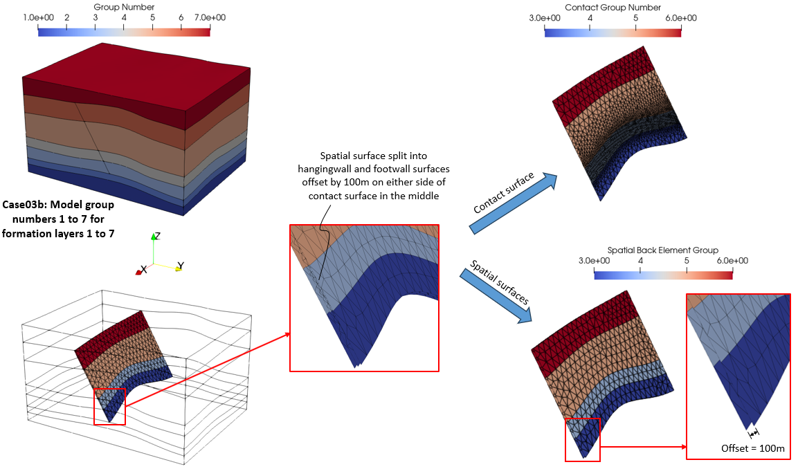
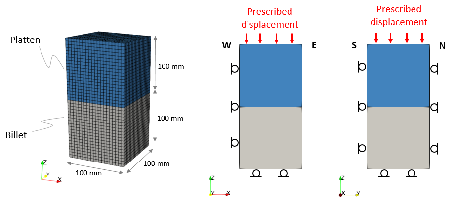
•Various geostatic initialization phases (gravity, tectonic, contact release, constitutive release) •Production simulation •Mechanical contact •Initial spatial grid data and spatial boundary |
|
•Case 1b Reservoir Poro-elasticity defined via Spatial_table |
•Young's modulus - porosity dependent spatial table |
|
•Geostatic initialization stages (gravity and tectonic) via implicit solver •Restart data |
||
•Case 3a HM Coupled (High Perm Fault) •Case 3b HM Coupled (Low Perm Fault)
|
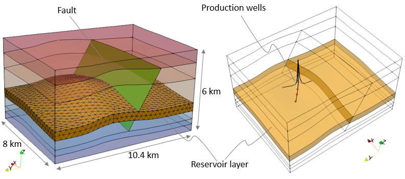
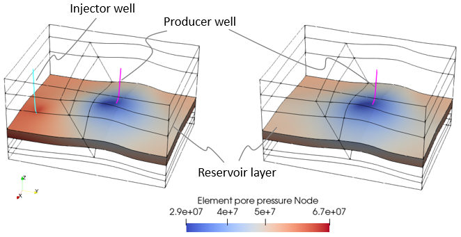
•Coupled HM simulation •Water level •Well element for producer well •High/Low perm contact fluid flow •Initial spatial grid data and spatial boundary |
|
•As Case 3a •Well element for producer and injector wells |
||
•As Case 4 •De-activation of porous flow groups |
||
•As Case 4 and Case04b respectively •Full implicit solver utilized for coupled hydro-mechanical solution •Node-node contact algorithm |
||
•Case 5 Mapping of Results to Spatial Surface and Output to Plot File |
•Read results plot file and output to new plot file •Mapping of results to imported Spatial surface definition |
|
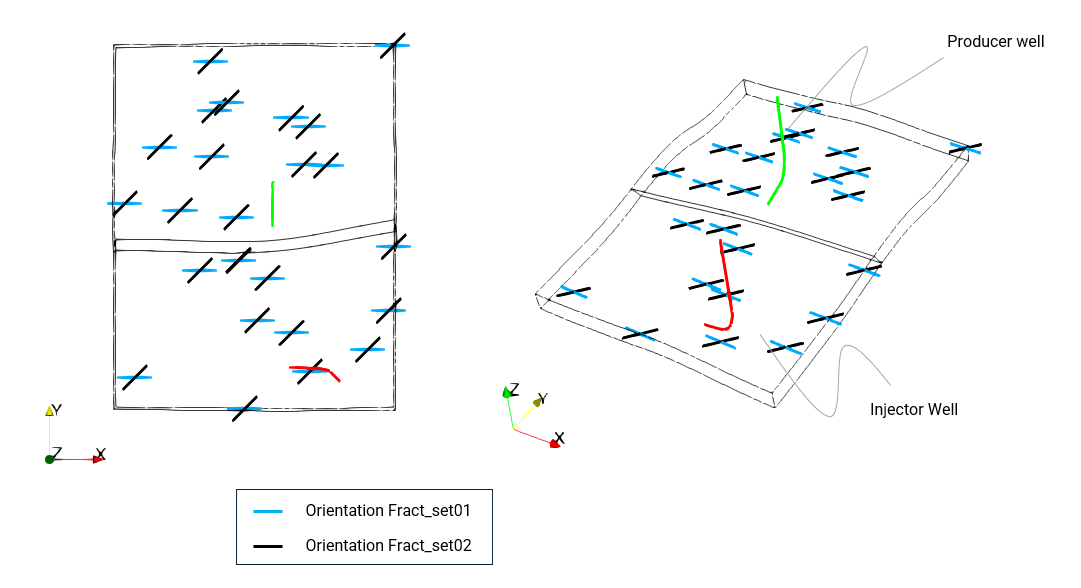
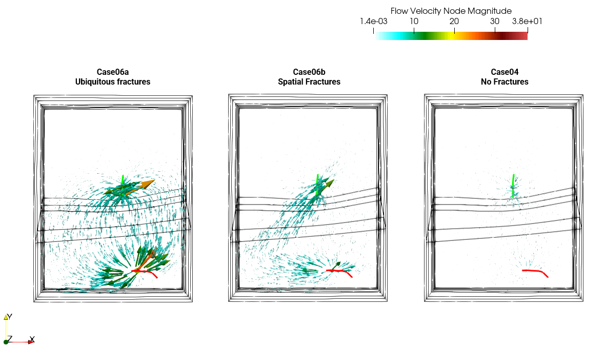
•Case 6 Reservoir with Fractures oCase06a - Ubiquitous fractures with homogeneous properties with fracture spacing of 5m oCase06b - Two corridors of fractures with spatial definition of fracture spacing ranging from 25m to 75m |
•Inclusion of embedded fractures in the reservoir and their influence on pore pressure distribution and flow |
|
Mechanical (3D) |
|
|
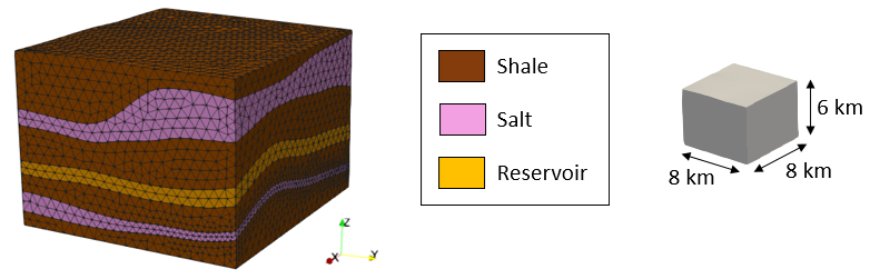
•Salt layers modelled via Herschel-Bulkley viscoplastic material •Various time unit updates via salt material constant K |
|
|
•Case 2 Faulted Case (Not available yet) |
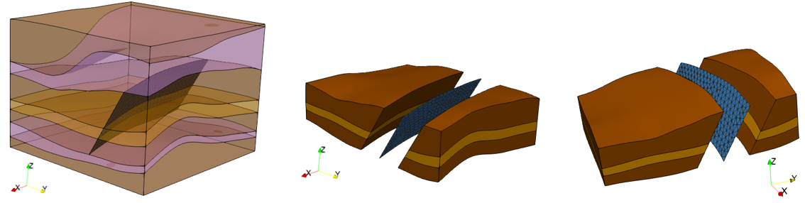
•Faulted model with contact |
|
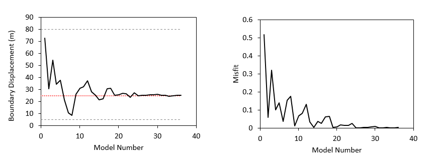
MEM_003 Boundary Optimisation and Super Element approach within the MEM Workflow |
Mechanical (3D) using ParaGeoInv |
|
•Case 2 Boundary optimisation using the Super Element approach (Currently unavailable) |
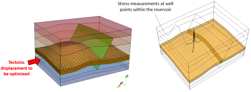
•Inverse analysis for initialisation stages using ParaGeoInv •Usage of Super element |
|
Implicit Solver |
||
Mechanical (3D) |
|
|
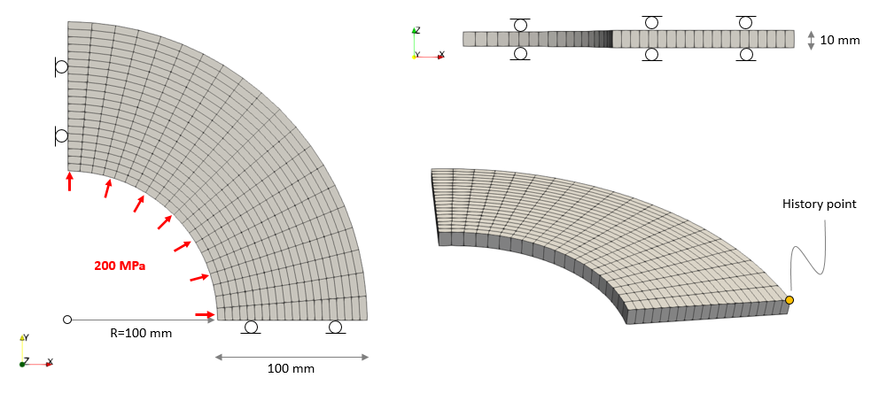
•Implicit solver |
|
|
Super Element (Currently unavailable) |
||
SuEl_001 Super Element Workflow |
Mechanical (3D) |
|
•Case 1 Workflow Example oStep 1 Create the Super Element oStep 2 Use the Super Element oStep 2b Use an Reflate the Super Element •Case 2 Usage of Coupled Freedoms |
•Super element workflow •Implicit solver •Coupled freedoms |
|
Wellbore Models |
||
Coupled THM (3D) |
|
|
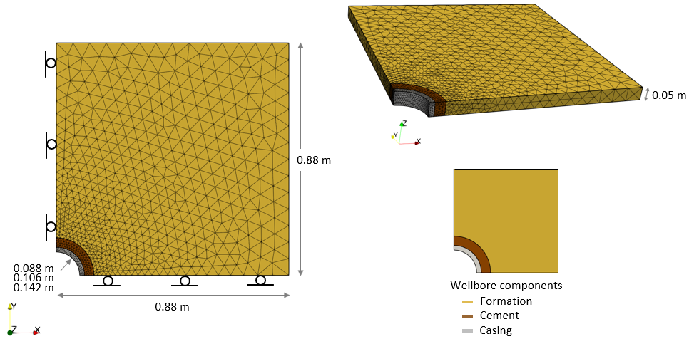
•Case01 Time-dependent Cement Hardening with Diagenetic Shrinkage |
•Coupled THM simulation •Deactivated porous flow in casing and cement •Contact between wellbore components •Time-dependent cement hardening material with increased yield strength •Cement hardening with diagenetic reaction resulting in volume shrinkage •Usage of transient time step growth in solution control |
|
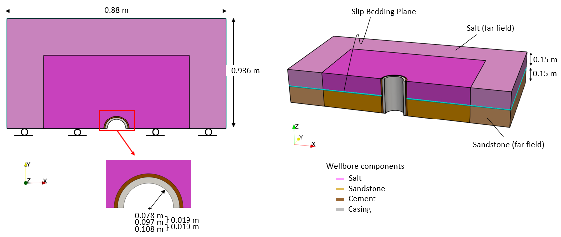
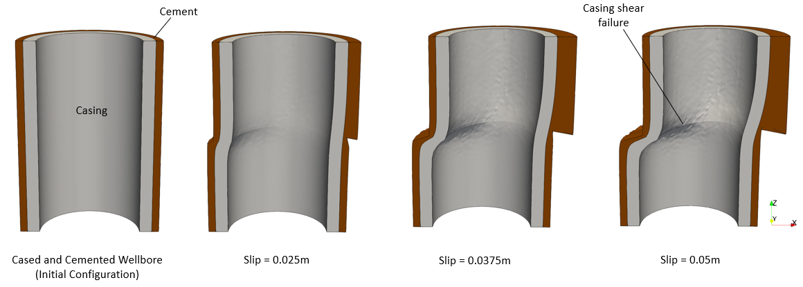
Wellbore_002 Casing Collapse due to Shear at Salt/Sandstone Bedding Plane |
Mechanical (3D) |
|
|
•Contact between salt/sandstone bedding plane •Large bedding plane slip (shear) causing casing collapse •Salt with Herschel-Bulkley viscoplastic material |
|