ParaGeo Examples

Contents
In this section several examples are discussed. Those comprise specific examples that can be used as a guidance on how to set up specific ParaGeo data structures or typical ParaGeo application models. As opposed to the ParaGeo Tutorial Examples section, a complete description of the datafile is not provided, thus focusing only on the relevant data structures.
INDEX
Title |
Analysis Type - Features List / Utility |
Model |
ParaGeo Data Structures/Typical Application Models |
||
Mechanical (3D) |
|
|
•Ex_001a Constant contact stiffness •Ex_001b Field dependent stiffness •Ex_001c Depth dependent stiffness •Ex_001d Contact stiffness dependent on underlying element stiffness |
•Contact data |
|
Mechanical (3D) |
|
|
•Multistage initialization •Pore pressure prescribed at mesh nodes (depletion) •Usage of restart files
|
|
|
Mechanical (3D) |
|
|
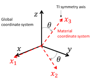
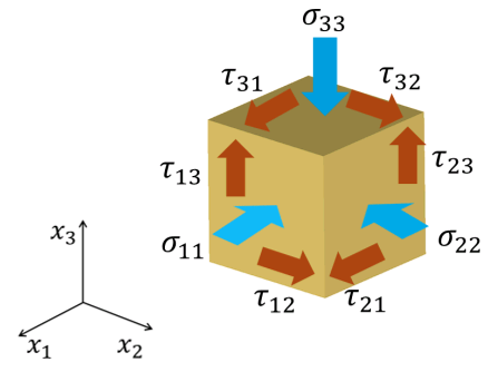
•Ex_003a_##deg (0°, 15°, 30°, 45°, 60°, 75°, 90°) Various rotations of material system |
•Transverse isotropic elasticity •Material system rotation |
|
Coupled HM (3D) |
|
|
|
•Usage of Constraint_relaxation data |
|
Mechanical (3D) / Coupled THM (3D) |
|
|
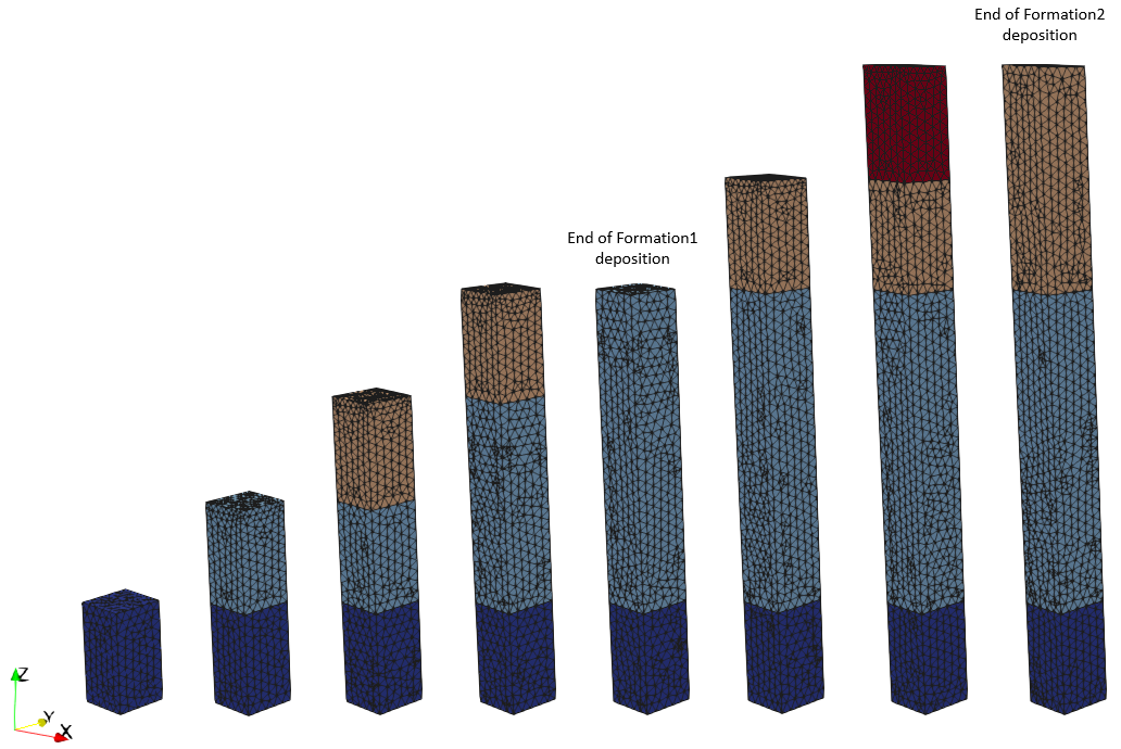
•Case 1 Sedimentation with Sub-layer •Case 2 Sedimentation with Layer Merge
|
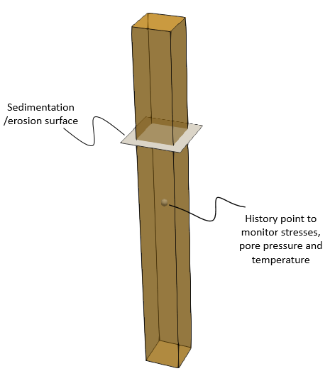
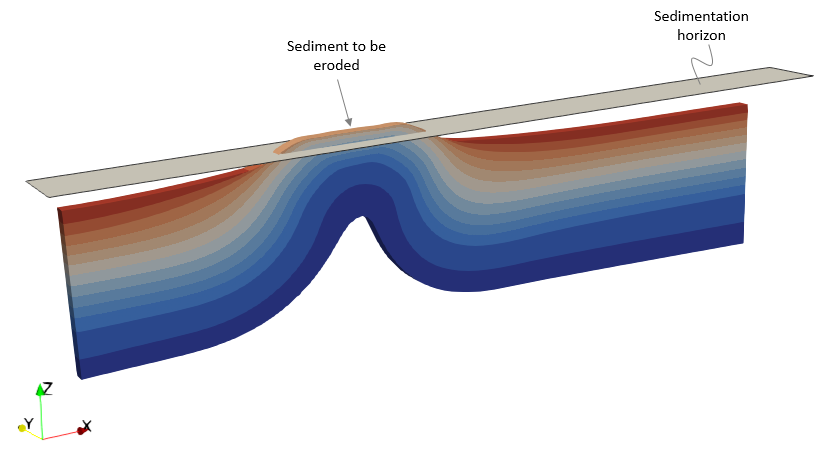
•Definition of special options for sedimentation and erosion |
|
•Case 3 Erosion in a Column (THM) |
|
|
|
||
Mechanical (2D) |
|
|
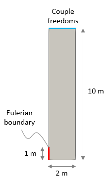
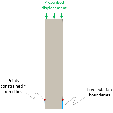
•Case 1 Prescribed salt inflow •Case 2 Prescribed salt outflow •Case 3 Two free Eulerian boundaries |
•Definition of Eulerian boundaries |
Case 1 and 2 (left), Case 3 (right) |
Thermal (2D) |
|
|
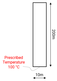
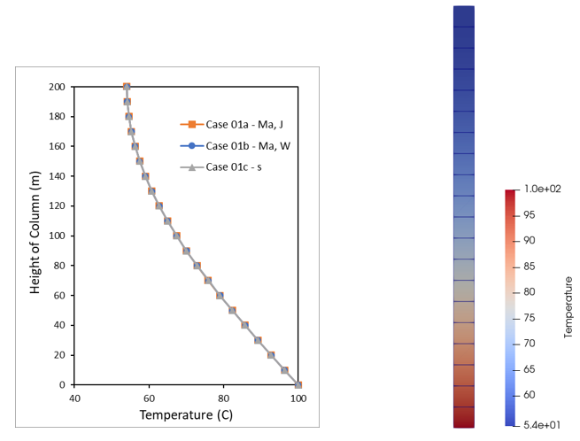
•Case 1 Heat Transfer in Ma and Seconds oCase01a - Input data in "Ma" time units and thermal units in "Joules" o Case01b - Input data in "Ma" time units and thermal units in "Watts" oCase01c - Input data in "seconds" time units |
•Using ParaGeo with different heat transfer units |
|
Coupled THM (3D) / Thermal (3D) / Flow (3D) |
|
|
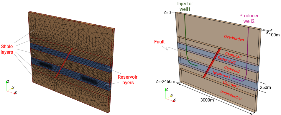
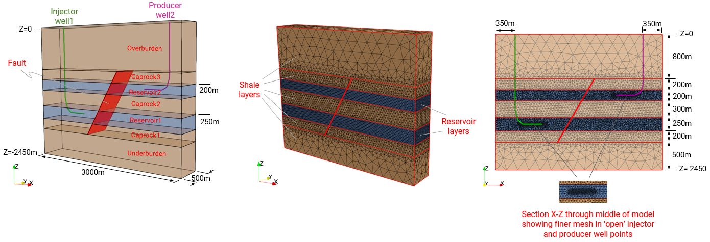
•Usage of well elements in THM injection and production models
|
|
|
•Contact advection along fault |
|
|
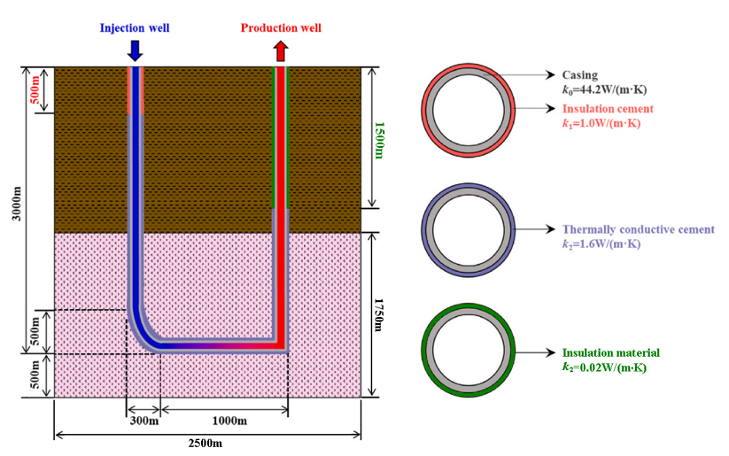
•Case03 U-Shaped Geothermal Well with Multiple Well Completions (Thermal) |
•U-shaped closed-loop well •Geothermal •Multi-layer, multi-well completions |
|
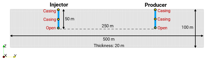
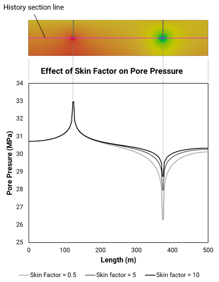
•Case04 Influence of Skin Factor on Well Elements using the Peaceman Model (Flow) |
•Peaceman flow model •Influence of skin factor |
|
ParaGeo Utility Mechanical (3D) |
|
|
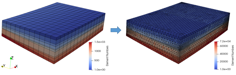
oEx_009_Sim01 - Three stage analysis (gravity initialization, single layer sedimentation, tectonic compression) oEx_009_Sim02 - Mapping of facies from HEX grid to TET mesh |
•Conversion of HEX mesh to TET mesh |
HEX mesh (left), TET mesh (right) |
Coupled HM (3D) |
|
|
•Case01 Confined Compression Test oCase01a - Fault prediction based on plastic strain threshold of 0.1. Fault elements with perm enhanced by 100.
oCase01b - As Case01a but plastic strain threshold of 5.0.
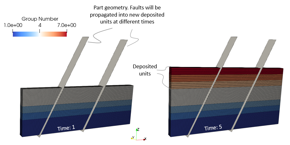
oCase01c - Fault is seeded at different location to Case01a using part geometry. Both perm enhancement and strength reduction considered.
oCase01d - As Case01c but only perm enhancement considered. |
•Continuum fault flow model •Fault prediction using plastic strain threshold value and perm enhancement •Fault seeding/insertion using part geometry |
|
|
||
Mechanical (3D) |
|
|
|
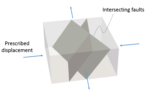
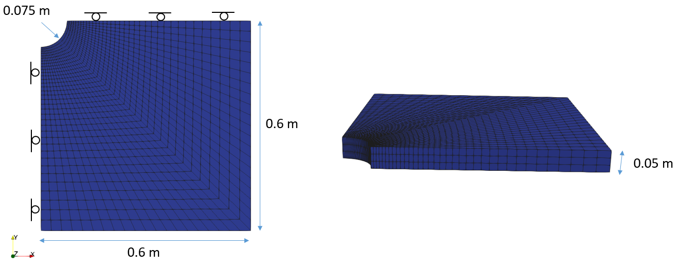
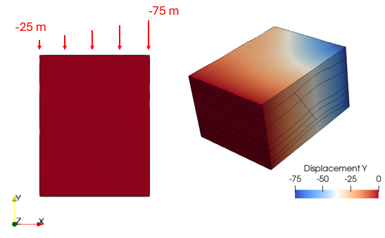
•Apply non-constant displacements to boundaries |
|
Mechanical (2D and 3D) |
|
|
|
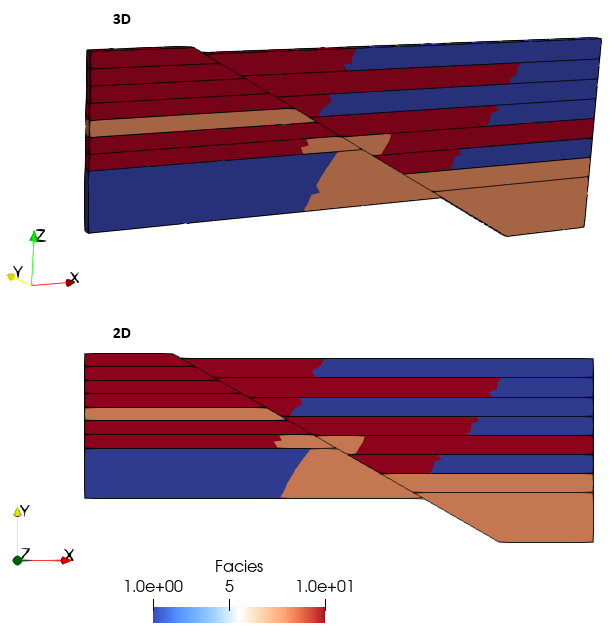
•3D to 2D spatial grid mapping |
Comparison of mapped facies distribution for 3D grid -> 3D geom and 3D grid -> 2D geom |
Coupled HM and Mechanical (3D) |
|
|
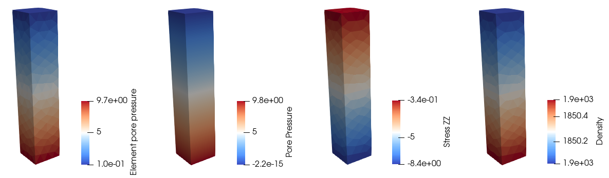
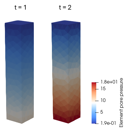
•Assumptions for each porous flow types •Discussion of results after initialisation •Output pore pressure variables |
|
|
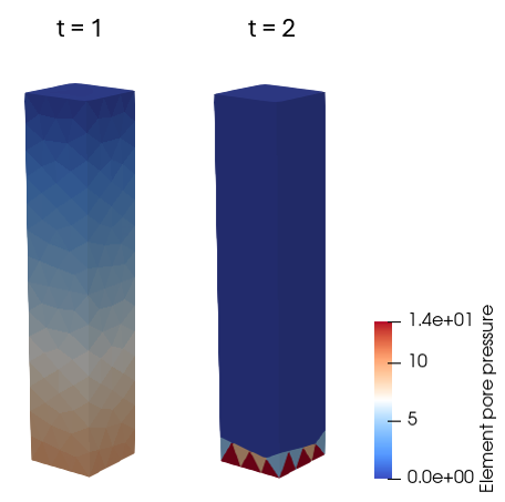
•Case02 Pore Pressure Loading for Different Porous Flow Types |
•Appropriate pore pressure loading for the different porous flow types |
|
Coupled (3D) |
|
|
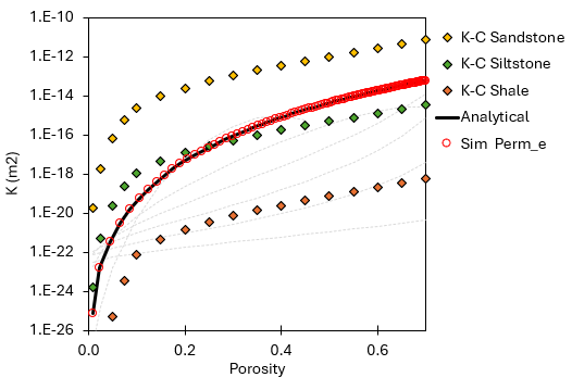
•Case01a - Power Law •Case01b - Power Law (with anisotropy and permeability cutoffs) •Case02 - Kozeny-Carman (with anisotropy) •Case03 - Exponential model (with anisotropy) •Case04 - Yang and Aplin model (with anisotropy) |
•Usage of different analytical porosity - permeability models •Usage of keywords to constrain the allowable range of permeabilities •Definition of permeability anisotropy for the analytical models |
|